


2SHU DWLQJ LQVWUXFWLRQV 0RWRU +RHV English
5
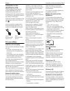
The symbols have the following
meanings:
Attention! Please
read the operating
instructions before
putting appliance into
operation!
Danger of injury from
rotating parts. Keep
hands and feet well
away from rotating
parts.
Always keep these symbols on the
appliance in a legible state.
7]QFSPWMRXLIYWIVk WKYMHI
Symbols are employed in the user’s
guide to indicate hazards or draw
attention to important information.
They have the following specific
meanings:
(ERKIV
(VE[W]SY VE XXI RXM SRXS WSYVG IWSJ
TSXIRXMEPHERKIVEWWSGMEXIH[MXLXLI
XEWO]SY EVI YR HIVX EOMRK EXX LIX MQI
[LMGL GSRWXMXYXI EH ERKIV XS TIVWSRW
'EYXMSR
9WIHXS LMKLPMKLXLE^EVHW[LMGLEVI
EWWSGMEXIH[MXLXLIEGXMZMX]XLEXMW
FIMRKHIWGVMFIH[LIVIF]HEQEKI
GSYPHSGGYVXSXLIETTPMERGI
2SXI
This indicates important information
and application tips.
9RTEGOMRK%WWIQFP]
'EYXMSR
(EQEKIHGEFPIWIXWGERPIEHXS
JEYPX]STIVEXMSRSJXLIQEGLMRI
;LIRYRTEGOMRKXLIQEGLMRIFI
GEVIJYPXLEXXLIWITEVXWHSRSKIX
FYGOPIHSVWUYEWLIH
When unpacking, check the
supplied contents. At the end of the
operating instructions or as a
supplement the assembly of the
appliance is presented in pictures.
&IJSVIJMVWXYWI
'EYXMSR
*SVXLITYVTSWISJXVERWTSVXEXMSR
XLIQEGLMRIMWWYTTPMIH[MXLSYX
IRKMRISMP
&IJSVIYWMRKXLIQEGLMRIJSVXLIJMVWX
XMQIJMPPYT[MXLIRKMRISMPWII
WITEVEXIIRKMRIMRWXVYGXMSRW
3TIVEXMRK
%PWSJSPPS[ XLIMRWXVYGXMSRWMRXLI
IRKMRILERHFSSO
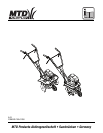
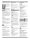
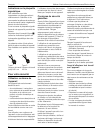
7IX XLILS IMRK HI T XL
Figure
The tilling depth can be set by adju-
sting the depth gauge (4).
7IXHITXLGSRXVSPPMRKFEV
Figure
■ Undo spring connector (
E
) and
bolt (
F
).
■ Set depth-controlling bar (4).
The lower the bar, the deeper
and slower the machine hoes.
■ Secure depth-controlling bar with
bolt and spring connector.
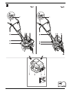
7IXXMRKXLIXVERWTSVXEXMSR
[LIIP
The transportation wheel (10) has
been set at the factory so that the
unit is positioned horizontally when
in an idle state. The tiller cannot be
operated until the wheel is moved
upwards.
8MPP MRK
Figure
■ Pull wheel holder (%) and press
upwards until it engages in the
tilling position.
■ Check that the wheel holder
engages correctly.
8VERWTSVXMRK
Figure
■ Pull wheel holder (%) and press
downwards until it engages in the
transport position.
■ Check that the wheel holder
engages correctly.
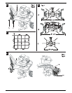
7IXKYMHMRKFEV
7IXLIMKLX
Figure
■ Undo lever/handle (3).
■ Set guiding bar at required height.
■ Tighten lever/handle again.
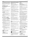
7IXLSIMRK[MHXL
8]TISRP]
Figure
(ERKIVSJMRNYV]
&IJSVIQEOMRKWIXXMRKWSRXLI
LSIMRKFPEHIW
r 7[MXGLSJJXLIIRKMRI
r ;EMXYRXMPEPPQSZMRKTEVXWLEZI
GSQIXSEWXERHWXMPPERHXLI
IRKMRILEWGSSPIHHS[R
r 6IQSZIXLIWTEVOTPYKXIVQMREP
;SVOZIV]GEVIJYPP]
By adjusting or dismounting the
hoeing blades, three different hoeing
widths can be set.
*EGXSV]WIXXMRK
■ Width 61 cm (B): undo spring
connector (2) and bolt (3), pull out
both outer blade pairs to the outer
holes and secure with bolts and
spring connectors.
■ Width 33 cm (C): undo spring
connector (2) and bolt (3), remove
both outer blade pairs.
2SXI
On Type 2 the tilling width cannot be
adjusted.
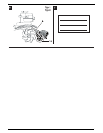
*MPPYT[MXLTIXVSPERH
GLIGOSMPPIZIP
(ERKIVSJI\TPSWMSRERHJMVI
%P[E]W JMPP YT MR XLI STIR EMV ERH [MXL
EW[MXGLIHSJJERHGSPHIRKMRI
2IZIVWQSOI[LIRJMPPMRKYT
2IZIVJMPPYTGSQTPIXIP]-JJYIP
SZIVJPS[WEPPS[XLISZIVJPS[XS
IZETSVEXIFIJSVIWXEVXMRK
!
!
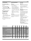
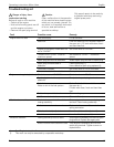
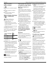
Hoeing width in cm Purpose
56 *)
Hoeing
61
33 Cultivation
!
!