


[4] DISASSEMBLY/ASSEMBLY
[4]-4. Gear case assembly
Repair
P 7/ 22
(1) According to the clause of [4]-3, Remove Gear case assembly. (Refer to Figs. 8, 9 and 10)
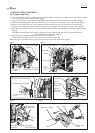
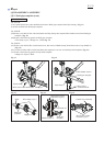
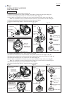
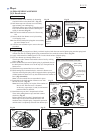
(2) Remove M8x10 + Hex bolt from the grease inlet of Gear case assembly. (Fig. 19)
(3) Remove Retaining ring R-26 with 1R006. (Fig. 20)
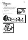
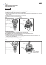
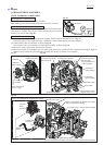
(4) Remove an assembled part of Spiral bevel gear 13*, Ball bearing 6000ZZ, Ball bearing 6000 and Retaining ring S-10
by tapping Gear case assembly with Plastic hammer. (Fig. 21)
Note: If the assembled part cannot be removed, use a heat gun or hair dryer to warm Gear case assembly.
(5) Remove Retaining ring S-10 with 1R291. (Fig. 21)
(6) Receive Ball bearing 6000 with 1R031, then press down the shaft end of Spiral bevel gear 13 using 1R282 with
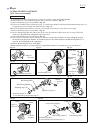
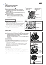
Arbor press. (Fig. 22) Refer to Fig. 23 for the components.
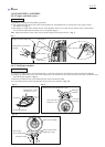
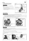
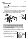
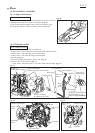
(7) Remove Retaining ring R-32 with 1R291. (Fig. 24)
(8) Preset Receive washer and 1R033 with M10-17 Hex nut to Cutter shaft complete* as drawn in Fig. 25, and give
the impacts using the plastic hammer. An assembled part of Cutter shaft complete* and Ball bearing 6201LLU is
removed. Refer to Fig. 26 for the components.
(9) Remove Ball bearing 6201LLU with 1R045.
*Neither Spiral bevel gear 13 or Cutter shaft set is supplied individually. It is supplied as a set “Cutter shaft set”.
Fig. 19
DISASSEMBLING
Fig. 21 Fig. 22
Fig. 20
Fig. 25 Fig. 26
Fig. 24
Fig. 23
M8x10
+ Hex bolt
1R031
Arbor press
M8x10
+ Hex bolt
Retaining ring R-26
Retaining
ring R-32
Spiral bevel gear 13*
Ball bearing 6000ZZ
Retaining ring S-10
Receive
washer
Gear case
assembly
M10-17
Hex nut
1R033
Retaining ring R-26
It was removed by the previous step (3).
Retaining ring R-32
It was removed by the previous step (7).
Ball bearing 6201LLU
Ball bearing 629ZZ
Cutter shaft complete*
O ring 32
Ball bearing 6000
Assembled part
Retaining ring S-10
Ball bearing
6000
Ball bearing
6000ZZ
1R282
Spiral bevel
gear 13*