


Repair
P 16/ 22
Fig. 71
Fig. 72 Fig. 73
Fig. 70
[4] DISASSEMBLY/ ASSEMBLY
[4]-11.
Stop switch section
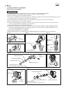
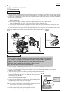
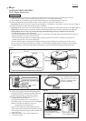
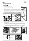
CHECKING STOP SWITCH
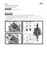
FUEL TUBE ROUTING
Check the continuity between the bullet terminals on the two lead wires
extending from Control lever with a circuit tester. (Fig. 70)
If Stop switch functions properly, there will be no continuity with
the switch ON and there will be continuity with the switch OFF.
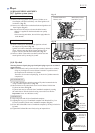
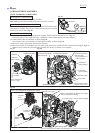
Set Tube complete* in place as shown in Fig. 71.
• Connect Tube 3-260 to Carburetor and Gasoline filter with Hose clamp.
• Connect Tube 3-150 to the long pipe of Primer pump.
• Connect Tube 3-120 to the short pipe of Primer pump.
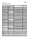
Also refer to Fig. 72.
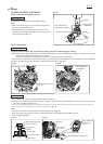
(3) Put Coil spring 8 and Clamp on Tube 3-150. (Fig. 71)
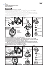
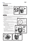
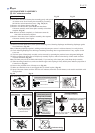
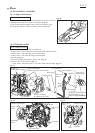
(4) Route Tube 3-150 as drawn in Fig. 72.
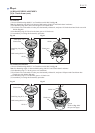
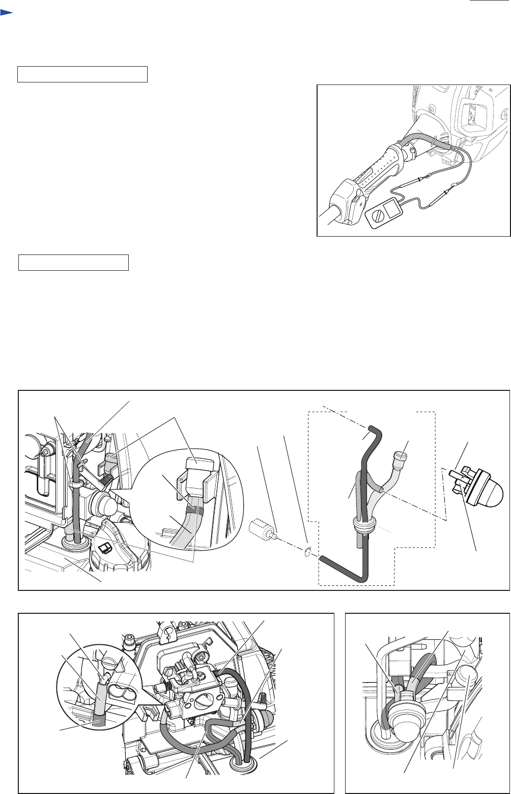
Route Tube 3-120 between Tube 3-150 and Cleaner plate assembly. (Fig. 73)
Tube 3-260 (black)
Holders of
Cleaner plate assembly
Fuel tank
Breather (to intake air into Tank)
Tube 3-150 (blue)
(to intake air into Tank)
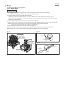
[4]-12. Fuel tube section
Tube complete
Breather
long pipe of
Primer pump
short pipe of Primer pump
to connect Tube 3-120
(Refer to Figs. 68 and 69.)
Hose clamp
Nipple of Carburetor
Tube 3-120
(blue)
Tube 3-120
(blue)
Tube 3-150 (blue)
Pipe
Breather
Tube 3-150
(blue)
Spiral tube
6-100
Spiral tube 6-80
Tube 3-260
(black)
Fuel tank
(to Carburetor)
Gasoline filter
Grommet
Tube
3-150
(blue)
Tube 3-260
(black)
Coil
spring 8
Clamp