


[4] DISASSEMBLY/ASSEMBLY
[4]-10. Carburetor section
Repair
P 14/ 22
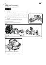
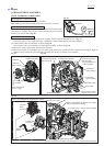
(1) Press down the tab of Cleaner plate assembly gently and separate
Air cleaner cover from Cleaner plate assembly by loosening
M5x20 Hex socket button head screw. (Fig. 1 of [4]-2.)
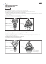
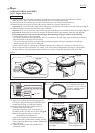
(2) Remove Air cleaner element. (Fig. 58)
(3) Remove two M5x60 Hex socket head bolts that fasten
Carburetor assembly and Cleaner plate assembly to Insulator
complete. (Fig. 59)
Note: Remove the bolts completely, or Carburetor cannot be
removed from Insulator complete.
(4) Remove three tubes from Carburetor assembly, then separate
Carburetor assembly from Engine.
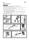
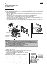
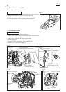
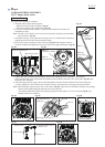
(1) Remove four Pan head screws, then separate Metering cover, Metering diaphragm and Metering diaphragm gasket
from Carburetor. (Fig. 60)
Note: If Metering diaphragm gasket is sticking on the adjacent part, remove it with care because it is easily broken.
(2) Check Metering diaphragm for shrinkage, hardening or breakage due to aged deterioration. If any, replace it with
a new one.
(3) The inner parts of Pump body assembly can be removed by separating the pan head screw designated in Fig. 61.
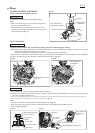
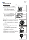
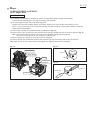
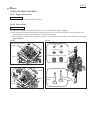
(4) Before mounting the inner parts of Pump body assembly in place, make sure that the tip of Inlet needle is neither
worn nor deformed. (Fig. 62)
Note: The inner parts are not available individually. If you need any of the inner parts, order Pump body assembly.
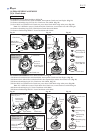
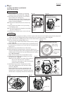
(5) When mounting Control lever, make sure that the upper end of Spring is firmly held in place under the projection of
Control lever. (Fig. 63)
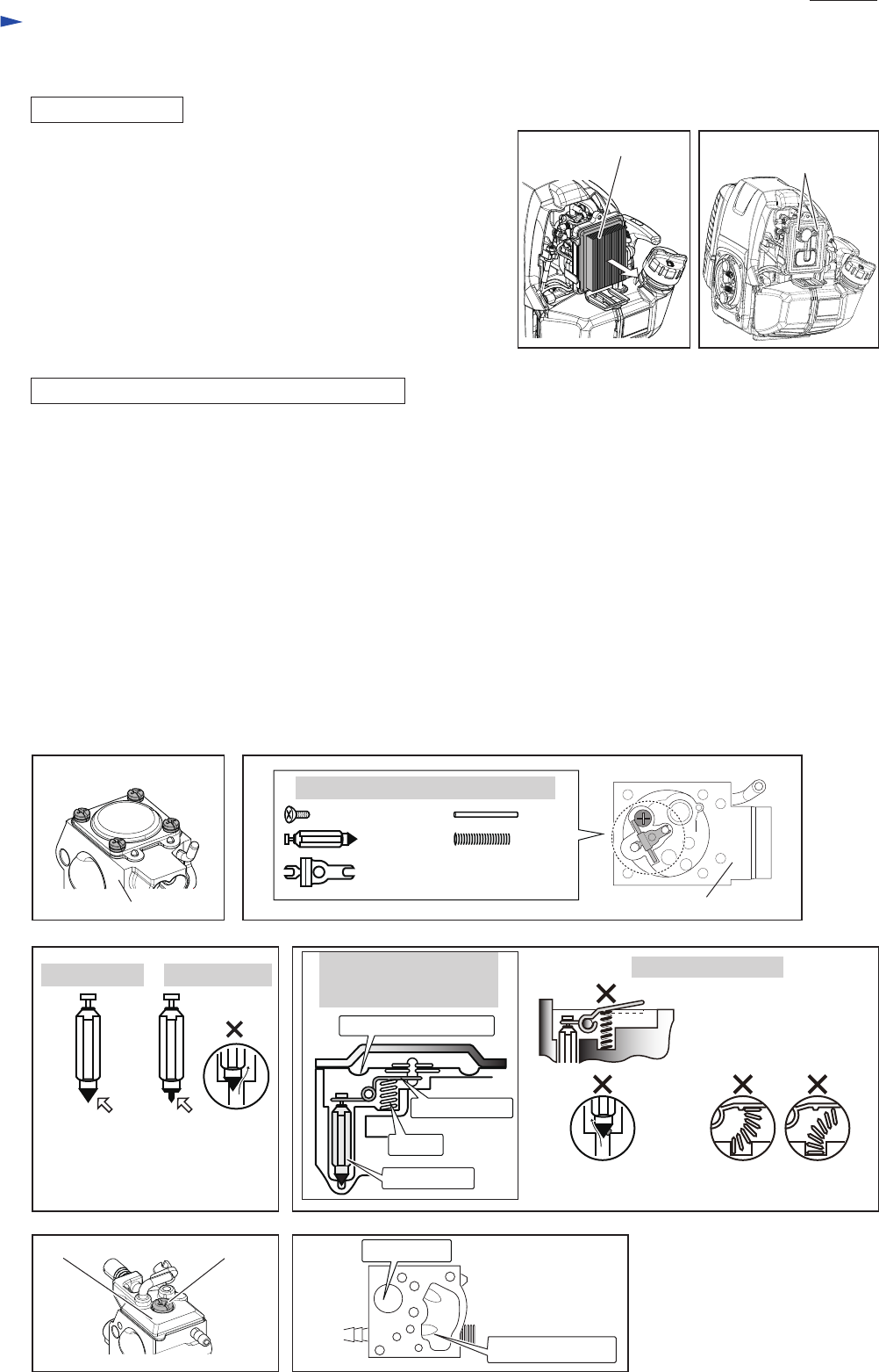
(6) Remove the pan head screw of Pump cover. (Fig. 64)
(7) Make sure that Inlet screen is not clogged, then set it back in place. (Fig. 65)
(8) Spray Carburetor cleaner in all the fuel lines of Carburetor, then after several minutes, wash out dirt and debris with
clean gasoline.
Fig. 60 Fig. 61
Fig. 65
Fig. 63
Fig. 64
Fig. 58 Fig. 59
DISASSEMBLING
DISASSEMBLING/ CLEANING CARBURETOR
Air cleaner element M5x60 Hex socket
head bolt (2 pcs.)
Pan head screw (4 pcs.)
Pan head screwPump cover
Carburetor
Pump body assembly
Fig. 62
An Inlet needle with
worn tip can cause
a pressure leak.
with good tip with worn tip
Correct assembling
of the inner parts of
Pump body assembly
Wrong examples
Metering diaphragm
Inlet needle
Spring
Control lever
Inlet screen
Carburetor body
Debris in valve seat can
cause a pressure leak.
The upper end of Spring
is out of place.
Control lever is not parallel
to Pump body assembly.
Pan head screw Pin
Inlet needle
Control lever
Spring
Inner parts of Pump body assembly