[4] DISASSEMBLY/ASSEMBLY
[4]-13. Engine block (cont.)
Repair
P 19/ 22
(8) Adjust Valve clearance as follows:
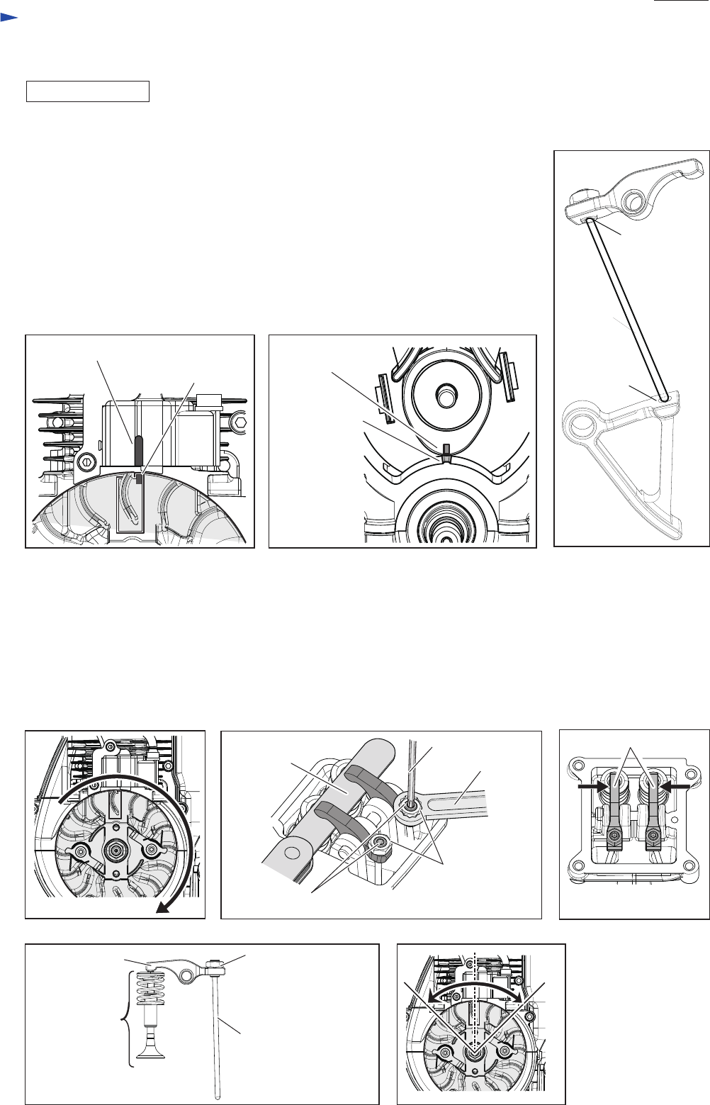
1. Align the marks on the following parts:
• Ignition coil and Flywheel complete (Fig. 81)
• Cam gear assembly and Cylinder block (Fig. 82)
2. Set two Cam lifters and two Rods 2.5 in place, then assemble two Rocker arm
assemblies to them.
Note: The ends of two Rods 2.5 have to be fit into the holes on Rocker arm assemblies
and Cam lifters. (Fig. 83)
3. Assemble Cam gear cover gasket and Cam gear cover to Cylinder block assembly by
tightening four M5x16 Hex socket head bolts firmly.
4. Revolve Flywheel assembly two turns clockwise (Fig. 84) and align the marks on
Flywheel complete and Ignition coil to move Piston to the upper dead point. (Fig. 81)
5. Tighten Hex nuts of Rocker arm assemblies, then loosen Adjusting screws of Rocker arm assembly.
Insert 0.08mm thick leaf of 1R366 into the clearance between Rocker arm and Valve section (Re: Fig. 85), then
adjust the valve clearance.
6. After checking the feeler gauge can be passed through the clearance and the clearance itself is not more than
0.12mm, tighten Hex nuts of Rocker arm assembly securely, and then remove the gauge from the clearance.
Note: While making two Rocker arms close to the center (Fig. 86), adjust the valve clearance with Hex nuts pushing
down by hand slightly (Fig. 87) and check the valve clearance.
After setting Spark plug in place and turning Flywheel left and right to 45
° two or tree times (Fig. 88), retry
checking
of the valve clearance.
Fig. 81
Fig. 84
Fig. 87 Fig. 88
Fig. 85 Fig. 86
Fig. 82
Fig. 83
DISASSEMBLING
Mark on Ignition coil
Mark on Flywheel
Mark on
Cam gear assembly
Hole on
Rocker arm
assembly
Rod 2.5
Hole on
Cam lifter
Mark on
Cylinder block
M5 Hex nut (2 pcs.)
1R170
Hex bit
Adjusting screw (2 pcs.)
0.08 mm thick leaf
of 1R366
Rod 2.5
Push down Hex nut of
Rocker arm
Rocker arm (2 pcs.)
Refer to Fig. 81 for
the cross section.
Valve section
Rocker arm


