


[4] DISASSEMBLY/ASSEMBLY
[4]-13. Engine block (cont.)
Repair
P 18/ 22
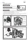
ASSEMBLING
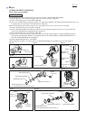
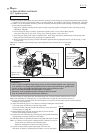
(1) Connect Piston with Crank shaft complete by inserting Piston pin into place; there is no front/back to Piston.
Note: Be sure to apply a little amount of Makita grease N No.2 to Needle roller bearing.
(2) Secure Piston pin by mounting Clip onto each end of Piston pin. Any setting direction is allowed.
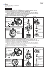
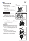
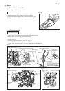
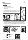
(3) Install Oil ring in the grooves of Piston; Side rail first, Spacer next, then the other Side rail.
Important: Be sure to fit the three rings with the ring gaps at 120 degrees to one another as shown in the left of Fig. 77.
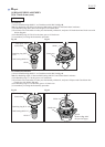
(4) Install Second ring first then Top ring in the groove of Piston.
Important 1: Be sure to fit the two rings with the ring gaps at 180 degrees to each other as shown in the right of Fig. 77.
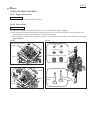
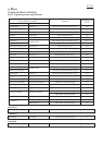
Important 2: Second ring has a taper face and must be installed with the large diameter facing Oil ring. (Fig. 78)
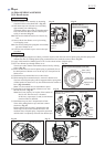
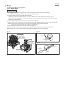
Distinguishing between Top ring and Second ring & Discriminating the larger diameter of Second ring:
If both of the two rings are new and unused,
• You can distinguish from their appearances; there is a T marking on the right upper end of Second ring as shown in
Fig. 75 while not on the upper end of Top ring.
• You can face the large diameter of Second ring by placing Second ring with the T marking on your right and
with the ring gap near you as shown in Fig. 79.
If both of the two rings are used and the T marking of Second ring is rubbed off, carefully press the side face of
the two rings to the inner wall surface of Cylinder. You will be able to distinguish the two rings or to discriminate
the large diameter of Second ring through the differences in contact feelings that the different side faces make.
Fig. 77
Top ring
Second ring
Fig. 78 Fig. 79
Fig. 80
Top ring, with barrel face
Second ring, with taper face
Side rail
Side rail
Spacer Oil ring
ring gap
ring gap
Note: Makita genuine second ring
has T marking on the right
upper end if it is not worn out.
Face the T marking toward
upward for assembly.
Second ring
T marking
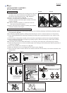
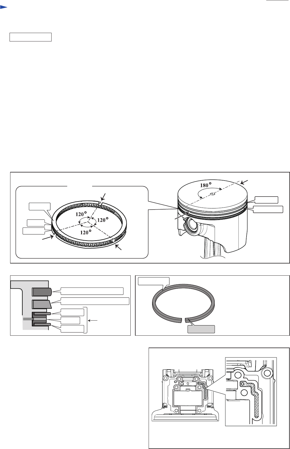
Crank case viewed
from the upper side
Gray colored portions:
where the adhesive should
be applied
Do not apply the adhesive
to the designated area.
Oil ring
ring gap
ring gap
ring gap
Side rail
Side rail
Spacer
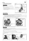
(5) Apply 4-cycle engine oil to the following portions:
Oil ring, Needle roller bearing that holds Piston pin,
Needle roller bearing of Crank shaft complete.
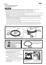
(6) Remove oil/grease from the mating surface of
Cylinder block and Crank case.
Then apply ThreeBond 1215/ 1216 carefully to
the mating surface of Crank case as shown in Fig. 80.
Note: Do not apply the adhesive to the area
designated by the enlarged view.
Apply 4-cycle engine oil to the sliding surface of
Piston section and Cylinder block assembly, and then
while compressing Piston rings, mount Cylinder block
onto Crank case.
(7) Tighten eight M6x25 Hex socket head bolts in
a crisscross pattern.
T