


CAUTION: Repair the machine in accordance with “Instruction manual” or “Safety instructions”.
[4] DISASSEMBLY/ASSEMBLY
[4]-1. Warning
Follow the instructions described below in advance before repairing:
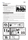
• Wear gloves.
• Remove the cutting tool from the unit, and if it is a saw blade, attach the blade cover to the blade.
• When the engine is hot from use, cool down the engine enough or you can get burned.
• Remove remaining fuel from Fuel tank and Carburetor completely. [FLAMMABLE MATERIAL KEEP FIRE AWAY]
• Remove Spark plug cap from Spark plug.
• Repair the engine on a stable workbench and in a clean workplace kept as free of dust and debris as possible.
• In order to avoid wrong reassembly, draw or write down where and how the parts are assembled, and what are the parts.
It is also recommended to have boxes ready to keep disassembled parts by group.
• Handle the disassembled parts carefully. Clean and wash them properly.
• If some bolts and screws are too tight, use an impact driver.
• Tighten the bolts and the screws to the specified torque as shown in "[4]-15. Tightening torque specifications".
• Each time after you mounted a main part of the engine such as the piston, check if it moves smoothly
without abnormal noise by manually turning the crankshaft.
• After completion of reassembly, check for loose parts or abnormal noise and vibration
by manually turning the crankshaft.
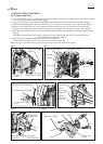
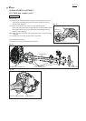
[2] HANDLING OF GASKET
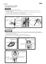
[3] LUBRICANT / ADHESIVE APPLICATION
Repair
P 2/ 22
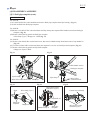
[1] NECESSARY REPAIRING TOOLS
DescriptionCode No. Use for
Once Gasket is removed:
(1) Clean up the mating surface where the gasket was installed to maintain its sealing performance.
(2) Replace it with a new one.
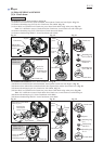
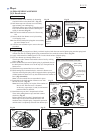
(1) Apply a little amount of Makita grease N No. 2 to Spiral spring in Recoil starter and the spline ends of Shaft in
Shaft pipe complete.
(2) When the inside of Gear case is cleaned, supply 11g of Makita grease N No. 2 from the grease inlet.
(3) Apply 4g of Makita grease N No. 1 to the entire portion of Shaft in Shaft pipe complete.
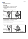
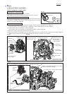
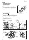
(4) Once Engine is disassembled, remove oil/grease from the mating surface of Cylinder and Crankcase complete,
then apply ThreeBond 1215/1216 to the mating surface for the reassembly.
Retaining ring pliers ST-2 for External ring1R004
press-fitting Cutter shaft set into Ball bearing 6000DDU
press-fitting Clutch drum into Ball bearing 6004LLU/6003LLU
Bearing setting pipe 20-12.21R028
removing Spiral bevel gear 14 from Ball bearing 609ZZ
Bearing setting pipe 28-20.21R031
removing/ installing Retaining rings
Retaining ring pliers RT-2N for Internal ring1R005 removing/ installing Cotter by using 1R389
removing Ball bearing 6000DDU from Cutter shaft completeBearing setting plate 10.21R033
removing Ball bearingsGear extractor (Large)1R045
Retaining ring pliers RT-2E for Internal ring1R006 removing/ installing Retaining rings
Air density tester1R127 diagnosing Carburetor
Round bar for arbor 20-1001R247 removing Clutch drum complete from Clutch case
Round bar for arbor 8-501R282
removing Spiral bevel gear 14 from Ball bearing 6000ZZ and
6000
removing Piston pin
Round bar for arbor 12-501R286 press-fitting Clutch drum complete into Clutch case
Retaining ring S and R pliers1R291 removing/ installing Retaining rings
Torque wrench shaft 7-23N.m
tightening Bolts to specified torque
1R219
Torque wrench shaft 2-6N.m1R254
Flywheel puller1R364 removing Flywheel
Feeler gauge set1R366 adjusting Ignition coil, Spark plug
Cotter removal attachment1R389 removing/ installing Cotter by using 1R005
10mm Hex socket bit
---
removing/ installing Flywheel
14mm Hex socket bit
---
removing/ installing Clutch
Wire brush
---
cleaning Spark plug