


Repair
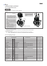
[3] -13. Fastening Torque
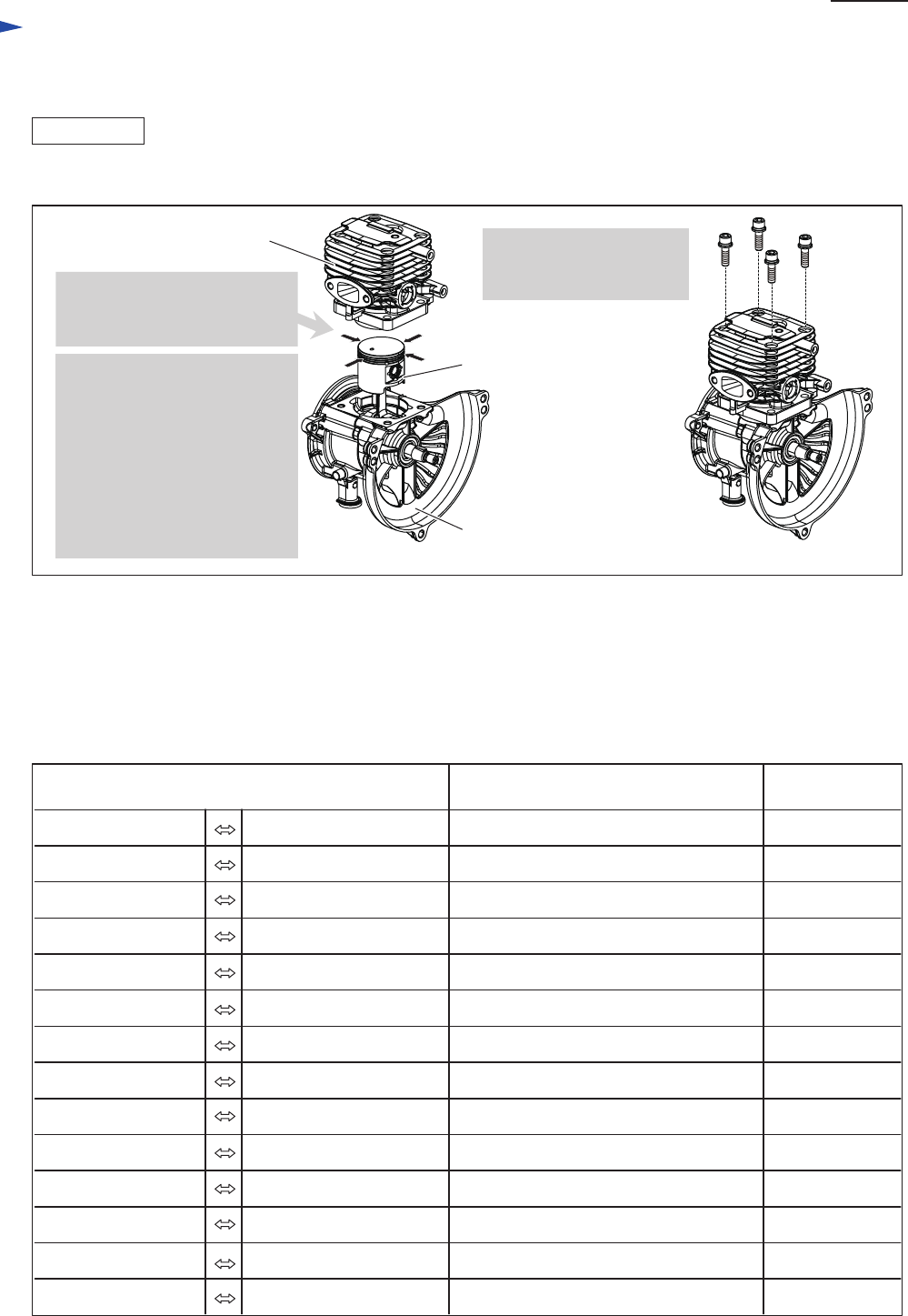
Fig. 50
Part description
Crankcase 1 Crankcase 2 M5x18 Hex Socket Head Bolt
Bolt and Screw
Fastening
Torque (N. m)
8
Cylinder Crankcase M5x18 Hex Socket Head Bolt 8
Fly wheel Crankshaft 1 M6 Nut 12
Coil Cylinder M4x20 Hex Socket Head Bolt 4
Muffler Cylinder M5x50 Hex Socket Head Bolt 8
Muffler cover Muffler M5x5 Screw 4
Clutch Crankshaft 2 M8 Screw (Left Hand Thread) 12
Plug Cylinder M10 10
Spur gear 9 Clutch drum M8 Screw (Left Hand Thread) 8
Grease nipple Gear case M6 4
Gear case cover Gear case M4x16 Hex Socket Head Bolt 4
Blade guard Guide bar M5x6 Screw 3.5
Plate Guide bar M5x8 Screw 3.5
Recoil starter Blower housing 4.5x14 Tapping Screw 2.5
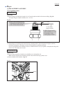
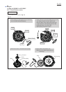
ASSEMBLIG
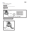
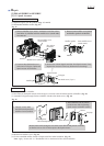
1. Insert Cylinder over Piston
while pressing Piston rings
toward the Piston’s center.
2. Tighten four Hex socket
head bolts in diagonal
order.
Note:
Pay attention not to let Piston
rings to move onto Nock pins
when it’s assembled to Cylinder
(Fig. 48).
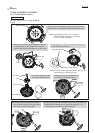
Piston rings will break
if Cylinder is mounted by force
over Piston rings that are
moved onto Nock pins.
Cylinder
Piston
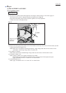
Crankcase assembly
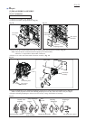
(6) Mount Cylinder to Crankcase assembly. (Fig. 50)
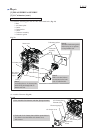
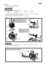
(7) Assemble Insulator to Cylinder.
Note: Apply “ThreeBond 1342” or “Loctite 242” to the thread of Hex socket head bolt.
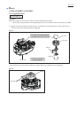
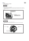
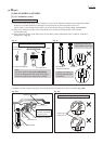
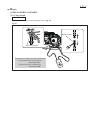
(8) Assemble Fuel tank.
Note: • Do not forget to mount Spacer between Fuel tank and Clutch case assembly.
• Apply “ThreeBond 1342” or “Loctite 242” to the thread of Hex socket head bolt.
P 25/ 25
[3] DISASSEMBLY/ASSEMBLY
[3] -12. Engine Block (cont.)