


P 11/ 25
Repair
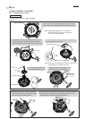
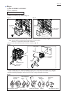
ASSEMBLING
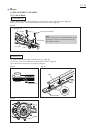
Ignition Coil
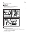
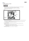
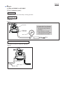
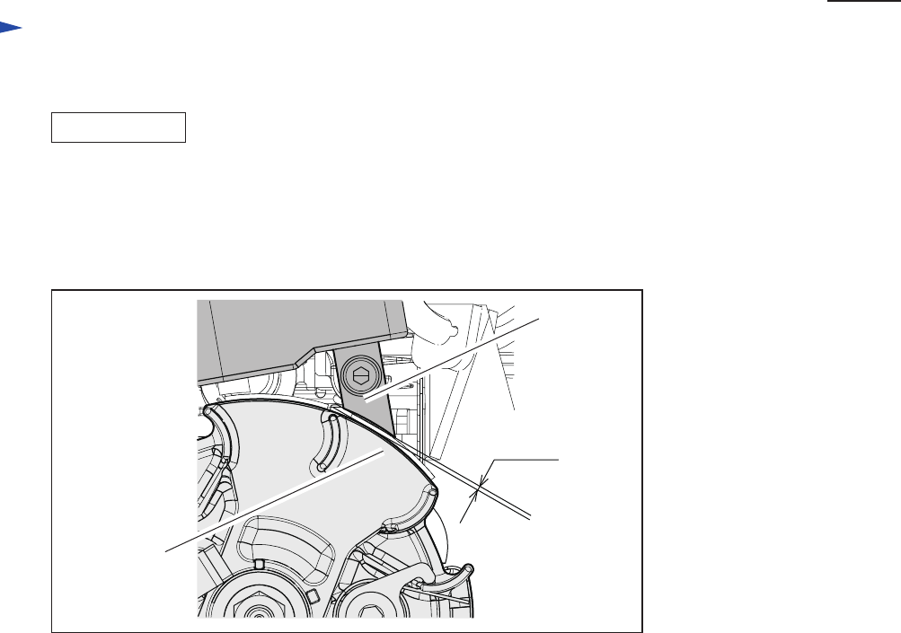
(1) Set Spacer on Cylinder and assemble Ignition coil on Spacer while inserting 0.3 mm feeler gauge of
1R366 between Fly wheel’s magnetized portion and Ignition coil. (Fig. 22)
Keep the inserted feeler gauge in this step till the Ignition coil is fully tightened
in order to fix the 0.3 mm gap precisely.
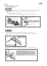
(2) Remove the feeler gauge after Ignition coil is fixed. Make sure that Fly wheel can be turned smoothly by hand
without interference by Ignition coil.
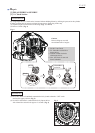
Note: Make sure to fix Ignition coil through the Spacer. High voltage cable and Lead wire must be fixed
into Rubber. Locate high voltage cable to Cylinder side.
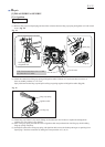
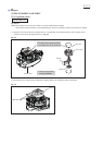
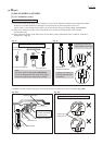
(3) Fix Rubber to Insulator.
Note: Make sure that the assembled High voltage cable does not interfere with Throttle in action.
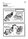
(4) Assemble Cylinder cover.
Note: Tighten Cylinder cover together with Spacer to Cylinder.
Thread locker must be applied to the thread of Hex socket head bolt which tightens that parts.
Apply “ThreeBond 1342” or “Loctite 242” as a thread locker.
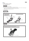
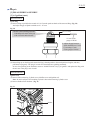
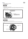
(5) Assemble Muffler cover.
Note: Apply “ThreeBond 1342” or “Loctite 242” as a thread locker.
Fig. 22
0.3 mm
Magnetized
portion of
Flywheel
Ignition coil
[3] DISASSEMBLY/ASSEMBLY
[3] -6. Ignition (cont.)