


9
Section 1: Assembly & Set-up
1/07/09
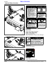
SC2660 & SC2672 Skid Steer Rotary Cutter 326-025M
Land Pride
Table of Contents
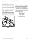
Skid Steer Requirements
The Rotary Cutter is designed to attach to Skid Steer
Loaders with the following minimum requirements:
SAE Lift Capacity
SAE Lift Capacity . . . . . . . . . . . . . . . . . . . . .1200 lbs.
Operating Hydraulic Pressure
Hydraulic Pressure Rating . . . . . . .1,500 - 3,000 PSI.
Hydraulic Flow Rate
Low Volume Motor & Hoses . . . . . . . . . 11 - 16 GPM.
Medium Volume Motor & Hoses . . . . . . 17 - 21 GPM.
High Volume Motor & Hoses. . . . . . . . . 22 - 27 GPM.
Hydraulic Connections
Hydraulic Hoses . . . . . . . . . . . . .2 - Hydraulic Outlets
Case Drain Hose . . . . . . . . . . . . .1 - Hydraulic Outlet
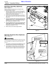
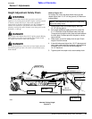
Protective Equipment
The Skid Steer MUST be equipped with a protective
door shield. A universal operator protective door shield
is available from Land Pride. Refer to Page 13 and 22
for additional information and installation.
Dealer Preparations
Pre-Assembly Checklist
All hardware from the factory has been installed. If a
part or fastener is temporarily removed for assembly
reasons, remember where it goes. Keep parts
separated.
Be sure the parts get used in the correct location. By
double checking while you assemble, you will lessen
the chance of using a bolt incorrectly that may be
needed later. Use Parts Manual to identify location of
parts you are unsure of where they are used.
All grease fittings are in place and lubricated.
Miscellaneous assembly tools: hammer, tape measure,
assortment of wrenches and spirit level.
Have fork lift or loader along with chains and safety
stands sized for the job ready for the assembly task.
Auxiliary weights (depending on Skid Steer size).
Have a minimum of 2 people at hand while assembling.
Safety decals are legible and undamaged.
Loose parts bag/box shipped with the Rotary Cutter.
IMPORTANT: Skid Steer must be equipped with a
case drain system.
IMPORTANT: Ballast may need to be added to your
Skid Steer to maintain steering control and to
prevent tipping of the Skid Steer. Refer to your Skid
Steer’s operator manual to determine if additional
ballast is needed.
Read and understand the operator’s manual for your
cutter. An understanding of how it works will aid in the
assembly and setup of your cutter.
This Rotary Cutter has been partially assembled at the
factory. However, some assembly will be necessary.
It is best to go through the Pre-Assembly Checklist
before assembling the cutter. Speed up your assembly
task and make the job safer by having all the needed
parts and equipment readily at hand.
Ensure that the intended Skid Steer conforms to the
requirements stated under the heading “Skid Steer
Requirements” on page 9.
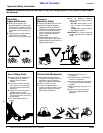
Uncrating
!
DANGER
Do not remove cutter from crate until after it has been securely
supported with an overhead crane, fork lift or other suitable
equipment. Cutter can fall and injury someone if crating
hardware is removed before properly supporting the deck.
1. Secure deck with an overhead crane, fork lift or other
suitable means before cutting shipping support
bands and unbolting cutter from shipping crate.
2. Cut bands securing parts bags to the shipping crate.
3. Remove bolts securing hitch to the shipping crate.
4. Cut center band securing hitch to shipping crate.
5. Carefully lower cutter onto its skids or onto support
stands capable of supporting the cutter.
6. Remove wood from under the front chain guard.
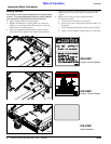
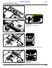
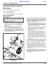
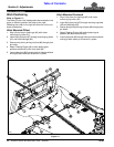
Float Chain Assembly
Refer to Figure 1-1:
1. (Not Shown) Unbolt and remove shipping brace bars
extending from hitch plate to center of deck.
2. Attach clevis end (#1) of float chains (#4) to hitch plate
with 9/16" clevis pins (#2) and cotter pins (#3). Bend
cotter pin legs to keep them from falling out.
3. Install other end of float chains (#4) to deck with
1/2" clevis pins (#5) and 1/8" cotter pins (#6). Bend
cotter pin legs to keep them from falling out.
Figure 1-1
Section 1: Assembly & Set-up