


24
Section 5: Maintenance & Lubrication
RCF2760 and RCF2772 Rotary Cutters 326-460M
12/15/15
Table of Contents
4. Inspect clutch and ensure that the scribed markings
made on the clutch plates have changed position.
Slippage has not occurred if any two marks on the
friction disc and plate are still aligned. A clutch that
has not slipped must be disassembled to separate
the friction disc plates. See “Clutch Assembly and
Disassembly” on page 24.
5. Tighten each of the 8 spring retainer nuts on the
clutch housing exactly 2 revolutions to restore the
clutch to the original setting pressure.
6. The clutch should be checked during the first hour of
cutting and periodically each week. An additional set
of scribe marks can be added to check for slippage.
See Figure 5-4 to adjust spring length.
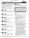
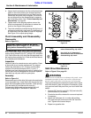
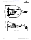
Clutch Assembly and Disassembly
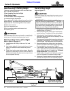
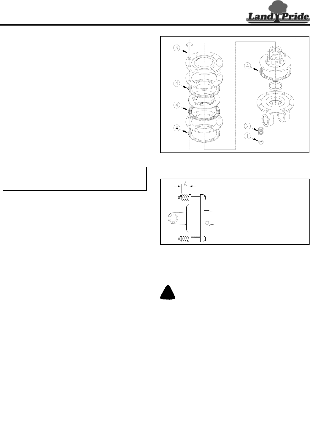
Disassembly
Refer to Figure 5-3:
See IMPORTANT NOTE above before disassembling
clutch. After measuring and recording each spring length,
remove spring retainer nuts (#1), springs (#2), and bolts
(#3). Each friction disc (#4) must then be separated from
the metal surface adjacent to it. Refer to the Parts Manual
for a detailed parts breakdown.
Inspection
Inspect all parts for excessive wear and condition. Clean
all parts that do not require replacement.The original
friction disc thickness is 1/8" (3.2mm) and should be
replaced if thickness falls below 3/64" (1.1mm). If
clutches have been slipped to the point of “smoking”, the
friction discs may be damaged and should be replaced.
Heat build-up may also affect the yoke joints.
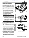
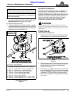
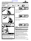
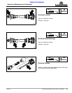
Assembly
Refer to Figure 5-4:
Reassemble each friction disc (#4) next to the metal plate
it was separated from. Install bolts (#3) through the end
plates and intermediate plates as shown. Place springs
(#2) over bolts (#3) and secure with nuts (#1).
Progressively tighten each spring retainer bolt until
correct spring height “A” dimension is obtained.
IMPORTANT: Refer to Figure 5-4. Be Sure to
measure and record length (“A”) of each clutch
spring before disassembling clutch.
Clutch Disassembly
Figure 5-3
Clutch Adjustment
Figure 5-4
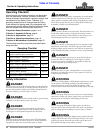
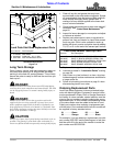
Skid Shoe Maintenance
Refer to Figure 5-5 on page 25:
!
WARNING
Excessive wear on skid shoes can damage side panels, cause
inadequate operation of cutter, and create a safety hazard.
Always replace skid shoes at the first sign of wearing thin.
There are skid shoes mounted on the cutter sides. Check
both skid shoes for wear and replace if necessary. Order
only genuine Land Pride parts from your local Land Pride
dealer.
1. Remove 3/8" hex whiz nuts (#3), 3/8" plow bolts (#2),
and skid shoe (#1) as shown.
2. Plow bolts should be checked for wear and replaced
if necessary.
3. Attach new skid shoe (#1) to cutter with existing
3/8" plow bolts (#2) and secure with 3/8" hex whiz
nuts. Tighten to the correct torque.
4. Repeat on opposite side.
23554
24600
A = Measured length of each spring
before disassembling slip clutch.
Use 1.319" for “A” dimension if
measurements were not taken befor
disassembling slip clutch.