


8
Section 1: Assembly & Set-up
RCF2760 and RCF2772 Rotary Cutters 326-460M
12/15/15
Table of Contents
Section 1: Assembly & Set-up
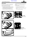
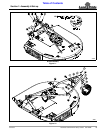
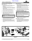
1. The cutter is shipped with 3/4" clevis pin (#12), pivot
tube (#1), and hairpin cotter (#11) assembled to hitch
straps (#5). Pivot tube (#1) should be removed only if
hitching to a Cat. 1 hitch.
2. Bushings (#2) are zip tied to top hitch (#13).
3. Remove hex flange lock nuts (#9A) and flat
washers (#10) from bolt (#6A).
4. Reattach A-frame brace bars (#5) with
5/8"-11 x 1 3/4" hex head bolts (#6A), bushings (#2),
flat washers (#10), and lock nuts (#9A). Tighten lock
nuts (#9A).
5. Attach 1 5/32" diameter holes in rear brace bars (#3)
to inside of rear deck lugs with 5/8"-11 x 1 3/4" GR5
bolts (#6B), 13/32" long bushings (#4), flat washers
(#10), and lock nuts (#9B). Tighten lock nuts (#9B).
6. Rotate A-frame/floating top hitch (#5 & #13) up and
rotate left rear brace (#3) up until holes in rear
braces (#3) align with hole in floating top hitch (#13).
7. Insert 3/4"-10 x 4 1/2" GR5 bolt (#7) into the left rear
brace (#3), floating top hitch (#13), and right rear
brace (#3).
8. Secure bolt with hex flange lock nut (#8). Draw lock
nut (#8) up snug and then back off 1/4 turn.
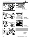
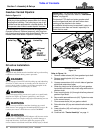
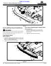
Tailwheel Assembly
Refer to Figure 1-2:
1. Attach tailwheel gauge arm (#1) to inside of rear deck
lugs with 5/8"-11 x 2" GR5 cap screws (#3C) and hex
nylock nuts (#5). Draw nylock nut (#5) up snug and
then back off 1/4 turn.
2. Install two 2 1/4" OD machine washers (#7) onto
tailwheel spindle (#9).
3. Insert tailwheel spindle into tailwheel pivot tube (#1).
4. Install third machine washer (#7) over tailwheel
spindle and secure with 3/8" x 2 1/2" roll pin (#8).
5. Attach bottom hole of tailwheel adjustment bar (#2) to
deck rear with 5/8"-11 x 2" GR5 cap screw (#3B), and
hex nylock nut (#5). Draw nylock nut up tight, do not
torque tight.
6. Tighten hex nut (#4) until lock washer (#6) is
squeezed flat.
IMPORTANT: See Detail A in Figure 1-1 on page 9.
Floating top hitch (#13) must be installed with
ears (#14) above rear brace bars (#3).
NOTE: After assembly of hitch, push on top of
A-frame assembly (#5). It should rotate backwards
and floating top link (#13) should rotate upwards. If
they are too stiff to rotate, loosen nuts (#8) until
floating top link (#13) rotates freely.
NOTE: Keep adjustment bar (#2) rotated up off the
deck to prevent scratching the paint while driving roll
pin (#8) in with a hammer.
Tractor Requirements
Tractor horsepower and hitch category should be within
the range noted below. Tractors outside the horsepower
range must not be used.
Tractor Horsepower Rating . . . . . . . . . . .35 to 130 HP
Hitch Category . . . . . . . . . . . . . . . . . . . . . . Cat I & II
PTO Speed. . . . . . . . . . . . . . . . . . . . . . . . . .540 RPM
PTO Shaft Type . . . . . . . . . . . . . . . . . 1 3/8"-6 Spline
!
WARNING
Ballast weights may need to be added to your tractor to
maintain steering control. Refer to your tractor operator’s
manual to determine proper ballast requirements.
Torque Requirements
Refer to “Torque Values Chart for Common Bolt Sizes”
on page 32 to determine correct torque values when
tightening hardware. See “Additional Torque Values” at
bottom of chart for exceptions to standard torque values.
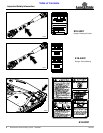
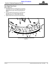
Uncrating Instructions
!
WARNING
Always secure cutter with an overhead crane, fork lift, or
other suitable lifting device before removing hardware bags,
shipping components, bands, lag screws, and hitch pins. The
cutter can suddenly fall causing serious injury or death.
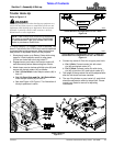
1. Secure cutter with a hoist or other lifting device
before removing shipping hardware.
2. Cut shipping straps securing driveline and hitch
straps (#5) to the shipping crate. Remove driveline
from shipping crate and lay gently hitch straps down
onto the shipping crate.
3. 5-pack only: Remove bar at the top connecting this
cutter to other cutters. Be sure to replace the bolts in
the cutter and to tighten it to the correct torque.
4. Remove lag screws securing cutter deck to crate.
5. Using lifting device, remove tension on hitch pins
securing clevis plates to shipping crate.
6. Remove hitch pins from clevis plates and lift cutter
from shipping crate.
7. Gently lower cutter onto the working area. Be careful
not to allow hitch straps (#5) to fall onto the plastic
manual tube.
3-Point Hitch Assembly
Refer to Figure 1-1 on page 9:
NOTE: When lowering cutter onto the working area,
keep hitch straps (#5) from falling onto the manual
tube and breaking the tube.
NOTE: Pivot tube (#1) is used only when
hooking-up to a Cat. ll 3-point hitch.