


13
Section 1: Assembly & Set-up
12/15/15
RCF2760 and RCF2772 Rotary Cutters 326-460M
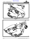
Table of Contents
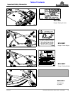
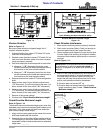
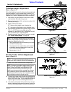
Driveline Shortening
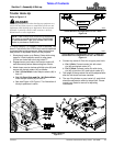
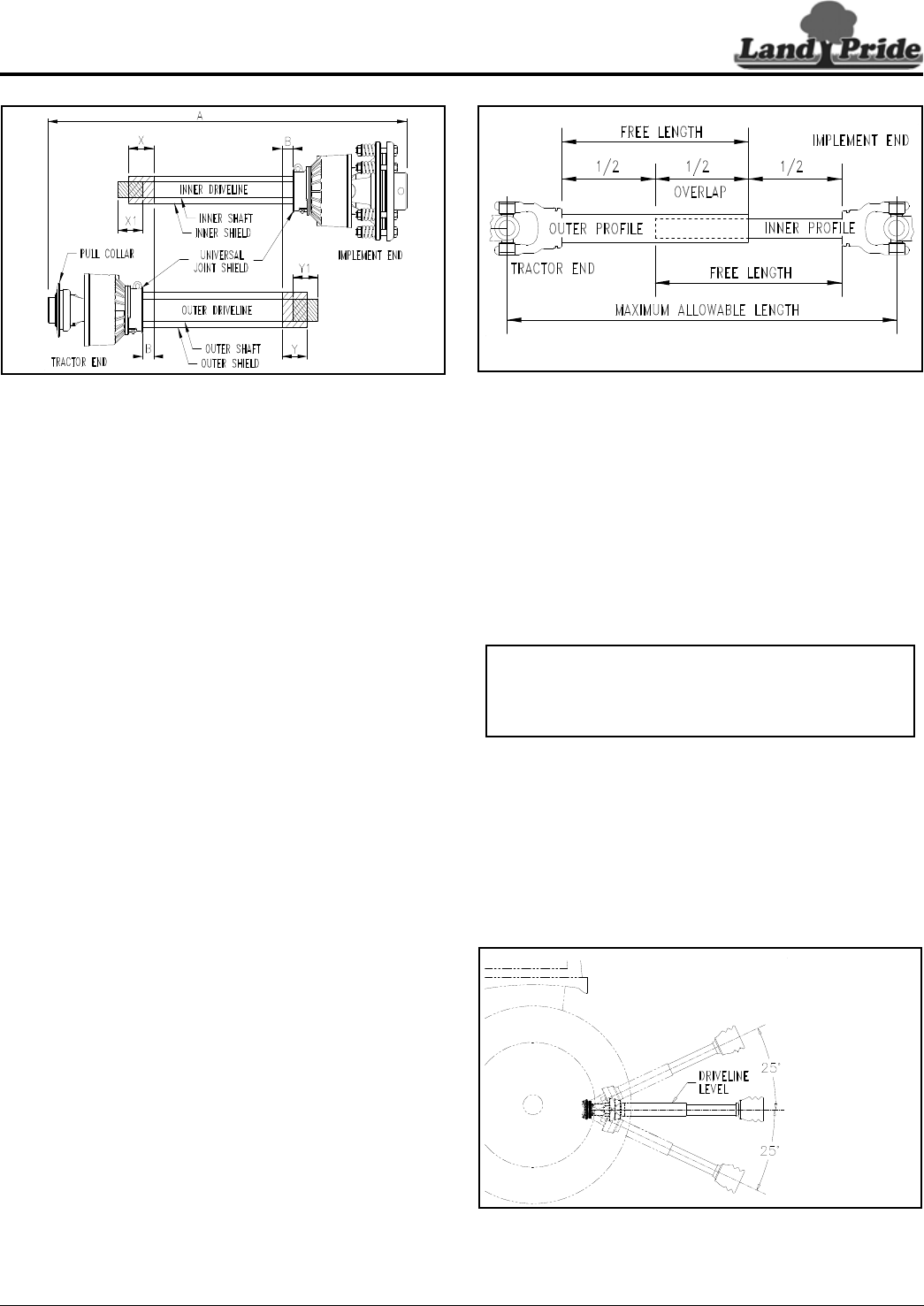
Figure 1-9
Shorten Driveline
Refer to Figure 1-9:
Be sure to check driveline collapsed length first. If
required, shorten driveline.
1. Unhook driveline from tractor PTO shaft. Pull outer
and inner drivelines apart.
2. Reattach outer driveline to tractor PTO shaft. Pull on
inner and outer driveline yokes to be sure universal
joints are properly secured.
3. Hold inner and outer drivelines parallel to each other:
a. Measure 1" (“B” dimension) back from outer
driveline universal joint shield and make a mark at
this location on the inner driveline shield.
b. Measure 1" (“B” dimension) back from the inner
driveline universal joint shield and make a mark at
this location on the outer driveline shield.
4. Remove driveline from tractor PTO shaft and gearbox
shaft.
5. Measure from end of inner shield to scribed mark
(“X” dimension). Cut off inner shield at the mark. Cut
same amount off the inner shaft (“X1” dimension).
6. Measure from end of outer shield to scribed mark
(“Y” dimension). Cut off outer shield at the mark. Cut
same amount off the outer shaft (“Y1” dimension).
7. Remove all burrs and cuttings.
8. Continue with “Check Driveline Maximum Length”.
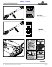
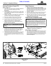
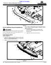
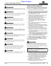
Check Driveline Maximum Length
Refer to Figure 1-10:
The driveline maximum allowable length must, when fully
extended, have a minimum overlap of profile tubes by not
less than 1/2 the free length with both inner and outer
profile tubes being of equal length.
1. Apply multi-purpose grease to the inside of the outer
shaft and reassemble the driveline.
2. Assemble the two driveline profiles together with just
1/2 overlapping of the profile tubes as shown. Once
assembled, measure and record maximum allowable
length here. ________
22311
Driveline Maximum Extended Length
Figure 1-10
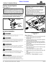
Check Driveline Interference
1. Make certain driveline yokes are properly attached.
2. Start tractor and raise Rotary Cutter just enough to
remove support blocks from under the cutter.
3. Slowly engage tractor hydraulic 3-point control lever
to lower cutter while checking for sufficient drawbar
clearance. Move drawbar ahead, aside, or remove if
required.
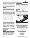
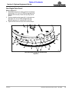
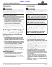
Refer to Figure 1-11:
4. With PTO off, raise implement fully up to make the
following checks below. If driveline exceeds any of
the limits listed, set tractor 3-point lift limiter at a
height that will keep the driveline within its lift limits
and to avoid premature driveline breakdown.
• Driveline does not exceed 25
o
up.
• Driveline does not exceed maximum allowable
length recorded in step 2 under “Check Driveline
Maximum Length”.
Maximum PTO Driveline Movement During Operation
Figure 1-11
24804
Outer Shielding has been removed for clarity.
IMPORTANT: Avoid premature driveline breakdown.
A driveline that is operating must not exceed an
angle of 25 degrees up or down while operating 3-
point lift.
24872