


27
Section 5: Maintenance & Lubrication
8/28/08
RC5015 & RC6015 (540 RPM) and RCM5015 & RCM6015 (1000 RPM) Rotary Cutters 318-047M
Land Pride
Table of Contents
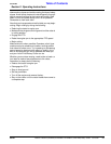
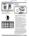
Disassembly
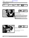
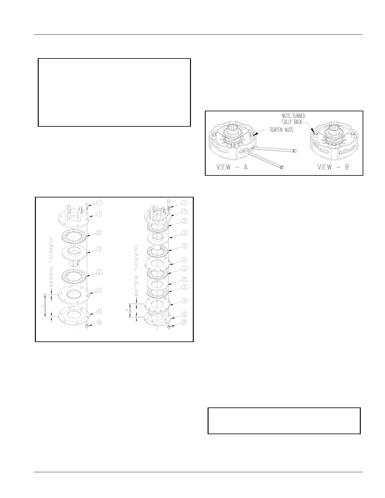
Refer to Figure 5-7:
1. Determine if you have a 2-plate clutch or 4-plate
clutch. Use matching illustration in Figure 5-7 below.
2. Measure from outside of belleville spring (#6) to
outside of plate (#4) on center line of all 6 bolts (#6).
Record these distances for reassembly.
3. Remove bolts (#7) evenly & belleville spring (#6).
4. Separate all friction disks (#2) from plates (#4 & #5),
hub (#3) and yoke flange (#1).
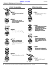
Type B Clutch Assembly
Figure 5-7
Inspection
Inspect all parts for excessive wear and condition. Clean
all parts that do not require replacement.The original
friction disk thickness is 1/8" (3.2mm) and should be
replaced if thickness falls below 3/64" (1.1mm). If
clutches have been slipped to the point of “smoking”, the
friction disks may be damaged and should be replaced.
Heat build-up may also affect the yoke joints.
Assembly
Reassemble each friction disk (#2) next to the metal
plate it was separated from. Install bolts (#7) through the
end plates and intermediate plates as shown and secure
with nuts (#8). Tighten each nut to the measured
distance (A) recorded in step 2 during disassembly.
IMPORTANT: If you have already loosened each
nut (#8) by 1 or 2 revolutions, retighten nuts before
taking measurement (A). Measure distance (A)
within (+/-.015") from outside of belleville spring (#6)
to outside of plate (#4) on center line of all 6 bolts
(#7) and record before disassembling the clutch.
These six measurements must be kept and reused
when reassembling the clutch to restore the
belleville spring to its original pressure setting.
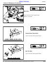
2-Plate Assembly 4-Plate Assembly
26637 26638
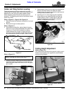
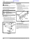
Type C Clutches
Clutch Run-In
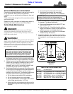
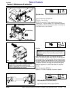
Refer to Figure 5-8 (View - A):
1. Using a pencil or other marker, scribe a line across the
exposed edges of the clutch plates and friction disks.
2. Tighten all 4 nuts uniformly until spring load is low
enough that the clutch slips freely with PTO
engaged.
Type C Clutch Run-In
Figure 5-8
3. Make sure the area is clear of all bystanders and
machine is safe to operate.
4. Start tractor and engage PTO for 2-3 seconds to
permit slippage of clutch surfaces. Disengage PTO,
then re-engage a second time for 2-3 seconds.
Disengage PTO, shut off tractor and remove key.
Wait for all components to stop before dismounting
from tractor.
5. Inspect clutch and ensure that the scribed markings
made on the clutch plates have changed position.
Slippage has not occurred if any two marks on the
friction disk and plate are still aligned. A clutch that
has not slipped must be disassembled to separate
the friction disk plates. See “Clutch Disassembly,
Inspection & Assembly” below.
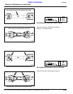
Refer to Figure 5-8 (View - B):
6. If no two marks on the friction disk and plate are still
aligned, Turn all 4 nuts fully back.
7. Allow clutch to cool to ambient temperature before
operating again. Clutch is now ready for use.
8. The clutch should be checked during the first hour of
cutting and periodically each week. An additional set
of scribe marks can be added to check for slippage.
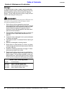
Clutch Disassembly, Inspection & Assembly
If clutch run-in procedure above indicated that one or more
of the friction disks did not slip, then the clutch must be
disassembled to separate the friction disks.
2369
6
IMPORTANT: Before proceeding, secure the clutch
firmly in a vise or other clamping device to prevent
injury.