


15
Section 1: Assembly and Set-up
8/28/08
RC5015 & RC6015 (540 RPM) and RCM5015 & RCM6015 (1000 RPM) Rotary Cutters 318-047M
Land Pride
Table of Contents
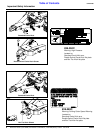
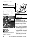
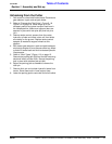
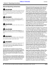
Refer to Figure 1-10:
2. Make certain the parking jack (#3) is properly
attached to the cutter and secured with attachment
pin (#8).
3. Back tractor within close proximity of cutter hitch.
4. Raise or lower the parking jack (#3) to align hitch
(#10) with bolt hole in swivel clevis (#9).
5. Back tractor up to cutter swivel hitch (#9) until hole in
hitch weldment with bushing (#10) aligns with holes
in swivel clevis (#9).
6. Insert 1" x 6 1/2" gr5 hex bolt (#1) through the cutter
swivel hitch (#9) and hitch weldment (#10). Secure
hex bolt with lock nut (#2). Tighten lock nut snugly to
remove all play. Do Not torque 1" lock nut.
7. Lower jack stand (#3) until hitch weight is removed.
Remove jack stand from hitch and store on left hand
deck wing storage base. Prevent water and freeze
damage by storing it so that the foot is level or lower
than the head, especially when the wing is folded up.
8. Attach hitch safety chain (#4) to the tractor. Adjust
chain length to remove all slack except what is
necessary to permit turning. Lock chain hook
securely to the safety chain.
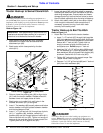
Tractor Hookup to Bar-Tite Hitch
Figure 1-10
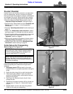
Driveline Installation
!
DANGER!
Do not engage tractor PTO while hooking-up and unhooking
the driveline or stand near a rotating driveline. A person’s body
and/or clothing can become entangled in the driveline resulting
in serious injury or death.
IMPORTANT: Jack attachment pin (#8) must be fully
inserted and secured before working on or around a
cutter that is not hooked to the tractor drawbar.
22262
!
CAUTION!
Always disengage PTO, engage parking brake, shut tractor
engine off, remove switch key and wait for blades to come a
complete stop before dismounting from tractor.
The main driveline may be either constant velocity type
or conventional type. Pull-collar couplers and retaining
bolts are used to connect the driveline to the tractor and
implement gearbox.
A driveline that is too long can damage the tractor,
gearbox and/or driveline. Always check driveline length
with cutter hitched to the tractor before engaging the
PTO.
Check Driveline Length
1. Park tractor and cutter in a straight line on a level
surface. Place gear selector in park, shut tractor
engine off, set park brake and remove switch key.
2. Attach pull-collar coupler to tractor PTO shaft and
bolted coupler to divider gearbox shaft. Skip to step 5
if driveline fits between tractor and implement.
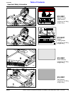
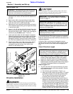
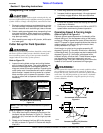
Refer to Figure 1-11:
3. The PTO driveline will require shortening if it does
not fit between tractor and cutter gearbox. Shorten
driveline as follows:
a. Pull driveline apart as shown in Figure 1-11.
b. Attach pull-collar coupler to the tractor PTO shaft
and bolted coupler to the divider gearbox shaft.
Pull on each driveline section to be sure the
universal joints are secured to the shafts.
c. Hold driveline sections parallel to each other to
determine if they are too long. The inner and outer
shields on each section should endapproximately
1" short of reaching the universal joint shield on
the adjacent section (see “B” dimension). If they
are too long, measure 1" (“B” dimension) back
from universal joint shield and make a mark at this
location on the inner and outer driveline shields.
IMPORTANT: The driveline must be lubricated
before putting it into service. Refer to “Lubrication
Points” on page 31.
IMPORTANT: Do not attempt to operate a 540 RPM
driveline at 1,000 RPM or a 1,000 RPM driveline at
540 RPM. Many tractors provide both 540 and 1,000
RPM PTO speeds. Check your tractor’s manual to
determine its capabilities.
IMPORTANT: Read and understand “Section 2:
Operating Instructions” beginning on page 18 before
operating the Rotary Cutter.
IMPORTANT: The Rotary Cutter must be hitched
with tractor and cutter aligned in a straight line on a
level surface. This arrangement provides correct
alignment between tractor and gearbox PTO shafts.