


26
Section 5: Maintenance & Lubrication
RC5015 & RC6015 (540 RPM) and RCM5015 & RCM6015 (1000 RPM) Rotary Cutters 318-047M 8/28/08
Land Pride
Table of Contents
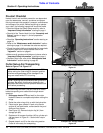
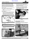
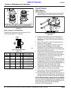
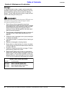
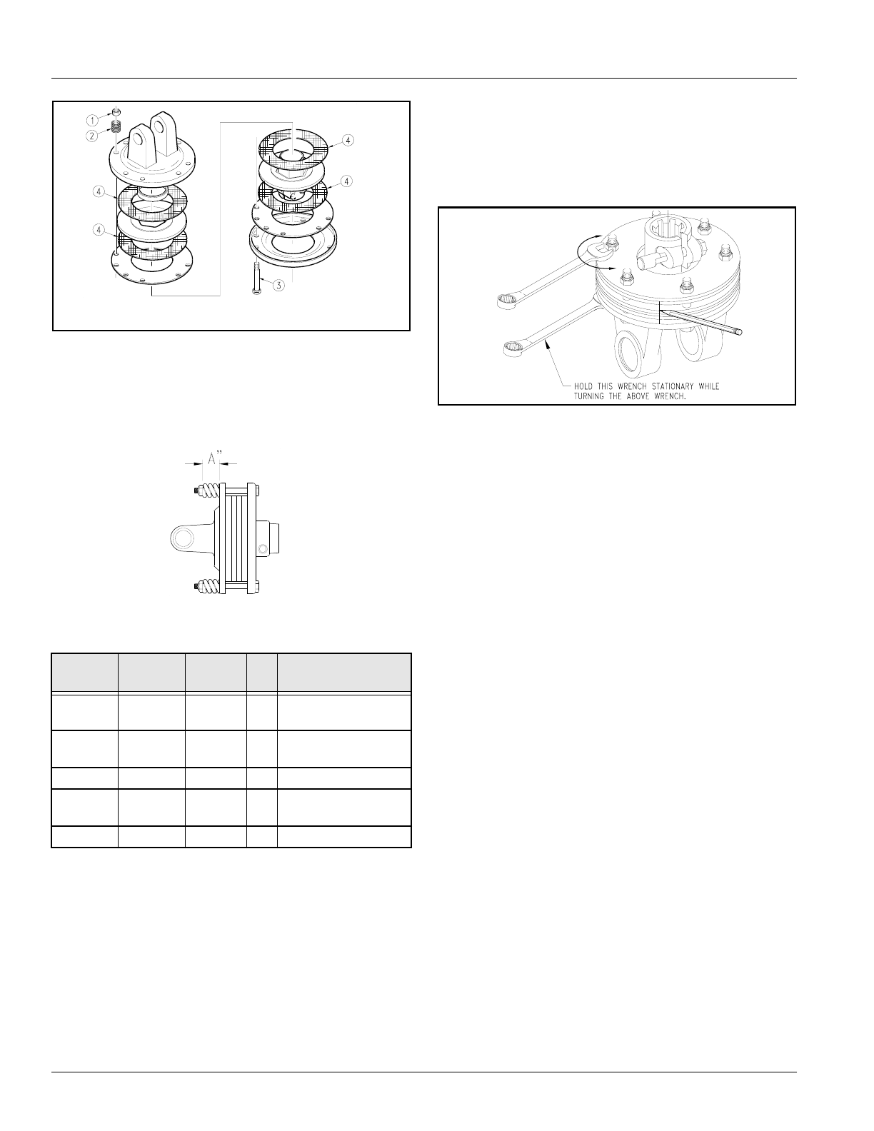
Type A Clutch Disassembly
Figure 5-4
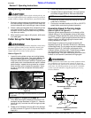
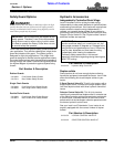
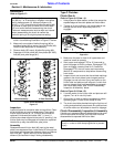
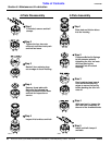
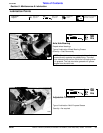
Refer to Figure 5-5 & Table Below:
Progressively tighten each spring retainer bolt until
correct spring height “A” is reached.
Type A Clutch Adjustment
Figure 5-5
Driveline
No.
Driveline
Location
PTO
Speed
Cat
No.
A (inches)
Spring Height
826-183C Center 540 4 1.15" (S/N 566919+)
1.12" (S/N 566918-)
826-184C Center 1000 4 1.09" (S/N 566919+)
1.02" (S/N 566918-)
826-478C Center 540/1000 5 1.32"
826-185C Wing 540/1000 4 1.175" (S/N 566919+)
1.14" (S/N 566918-)
826-481C Wing 540/1000 5 1.32"
14714
IMPORTANT: Keep track of order and orientation of
your clutch components during disassembly
24600
Type B Clutches
Clutch Run-In
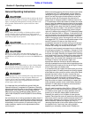
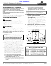
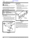
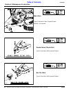
Refer to Figure 5-6:
1. Using a pencil or other marker, scribe a line across the
exposed edges of the clutch plates and friction disks.
Type B Clutch Run-In
Figure 5-6
2. Carefully loosen each of the 6 nuts by exactly 1
revolution. It will be necessary to hold hex end of
retainer bolt in order to count the exact number of
revolutions.
3. Make sure the area is clear of all bystanders and
machine is safe to operate.
4. Start tractor and engage PTO drive at idle for 2-3
seconds to permit slippage of friction plates.
Disengage PTO, shut off tractor and remove key.
Wait for all components to come to a complete stop
before dismounting from tractor.
5. Inspect clutch to ensure that the scribed markings
made on the clutch plates and friction disc have
changed positions. If any two marks are still aligned,
then the clutch did not slip as it should. Skip to
step 8 if all clutch plates slipped.
6. If the friction clutch did not slip, loosen the nuts one
more revolution. Make sure the nuts have full thread
engagement on the bolt and then repeat steps 4 - 5.
7. A clutch that does not slip must be disassembled to
separate the friction disk plates. See “Clutch
Disassembly, Inspection & Assembly” below.
8. Tighten each of the nuts on the clutch back to their
original location to restore clutch pressure.
9. Allow clutch to cool to ambient temperature before
operating again. Clutch is now ready for use.
10. The clutch should be checked during the first hour of
cutting and periodically each week. An additional set
of scribe marks can be added to check for slippage.
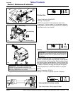
Clutch Disassembly, Inspection & Assembly
The clutch must be disassembled into its separate friction
disks if clutch run-in procedure above indicated that one or
more friction disks did not slip. See disassembly
instructions on the following page.
2661
8