


19
Section 2: Operating Instructions
8/28/08
RC5015 & RC6015 (540 RPM) and RCM5015 & RCM6015 (1000 RPM) Rotary Cutters 318-047M
Land Pride
Table of Contents
Transporting The Cutter
!
CAUTION!
When traveling on public roads at night or during the day, use
accessory lights and devices for adequate warning to operators
of other vehicles. Comply with all federal, state and local laws.
1. Be sure to reduce tractor ground speed when turning
and leave enough clearance so the cutter does not
contact obstacles such as buildings, trees or fences.
2. Select a safe ground speed when transporting from
one area to another. When traveling on roadways,
transport in such a way that faster moving vehicles
may pass you safely.
3. When traveling over rough or hilly terrain, shift tractor
to a lower gear.
Cutter Set-up For Field Operation
!
WARNING!
The following operational procedures should be carried out by
the tractor operator. Other persons should be cleared of the
area even during cutter set-up. Cutter operation should be
stopped when in the vicinity of other persons.
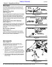
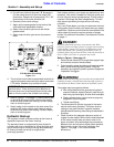
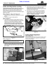
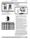
Refer to Figure 2-3:
1. Inspect the wing blade carriers and cutting blades
prior to lowering the wings. The cutting blades may
become locked together (overlapped) when the
wings are raised to transport position. Operating the
cutter under such circumstances will result in severe
deck vibration. Inspect the wing decks for a locked
blade condition prior to power-on operation. Use a
pry bar or other tool to separate the blades when
necessary.
Wing Deck Blade Positioning
Figure 2-3
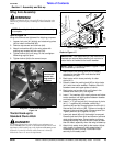
Refer to Figure 2-1 & Figure 2-2 on page 18:
2. Fully raise the wings to release any tension on the
transport lock bar as shown in Figure 2-1. Remove
hairpin clip (#1) from both the left and right cylinder
pins (#4).
3. Rotate end of transport lock bar (#3) to the storage
pin (#2) as shown in Figure 2-2. Secure with hairpin
clips (#1).
22169
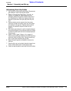
Wing Deck
Cutting Blades
Blade Carrier
NOTE: The cutter height is controlled with a hydraulic
lift cylinder.
4. Lower wing sections to the down position.
5. Increase throttle to approximately 1/4 engine speed
and slowly engage driveline. Also see note below.
6. Ensure that all power shafts are rotating and that the
cutter has no vibration.
7. Continue to increase throttle to full 540 or 1000 PTO
speed before commencing forward operation.
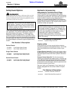
Operating Speed & Turning Angle
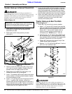
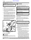
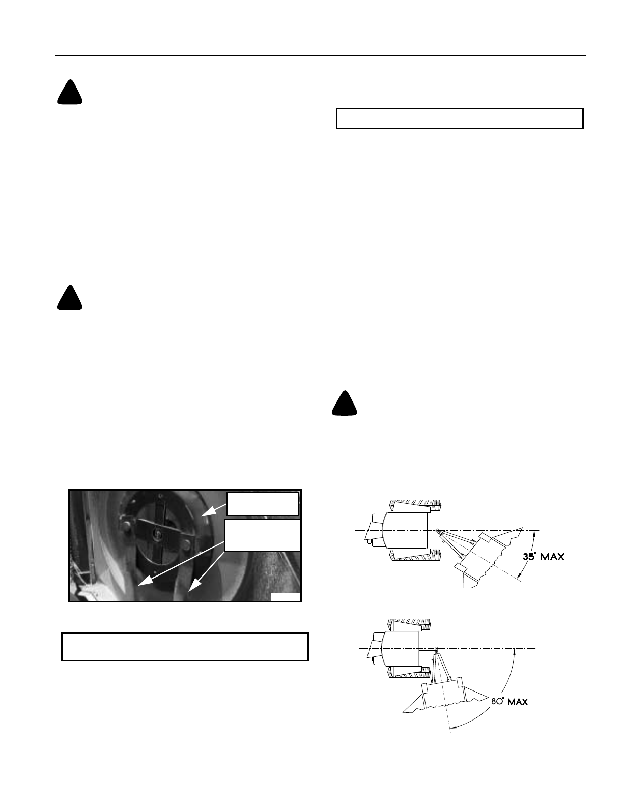
Refer to Figure 2-4 & Figure 2-5:
Optimum ground speed depends on the density of the
material being cut, the horsepower rating of the tractor
and terrain. Always operate the tractor at the cutter’s full
rated PTO speed in a gear range that allows the cutter to
make a smooth cut without lugging the tractor down,
usually between 2 to 5 mph.
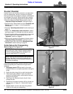
Avoid tractor-to-cutter turning angles exceeding 35
degrees (Figure 2-4) if the main driveline is a standard
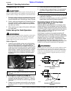
conventional shaft. Turning angle may be increased to 80
degrees (Figure 2-5) if the cutter is equipped with a
constant velocity driveline shaft. These extreme angles
are intended for intermittent usage only and not
prolonged usage. Plan your field cutting to minimize the
number of turns as well as extreme turning angles.
!
WARNING!
Do not operate this cutter under any terrain conditions where,
on a continuous cut, the wing angle exceeds 45 degrees up.
Ensure that the wing wheels are in continuous ground contact
at all times. Use the float position of your tractor’s hydraulic
system to provide automatic wing float position for varying
terrain conditions.
Conventional U-Joint Driveline
Figure 2-4
Constant Velocity (CV) Driveline
Figure 2-5
NOTE: Use tractor’s PTO soft start option if available.
11934
20795