


13
Section 1: Assembly and Set-up
8/28/08
RC5015 & RC6015 (540 RPM) and RCM5015 & RCM6015 (1000 RPM) Rotary Cutters 318-047M
Land Pride
Table of Contents
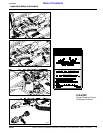
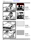
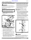
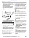
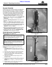
Tractor Hookup to Standard Clevis Hitch
Figure 1-7
Refer to Figure 1-7:
1. Make certain the parking jack (#3) is properly
attached to the cutter hitch and secured with
attachment pin (#8).
2. Back tractor within close proximity of cutter
clevis (#11).
3. Raise or lower the parking jack (#3) to align clevis
(#11) with the tractor drawbar. Drawbar should fit
between lower and upper plates of clevis.
4. Back tractor up to cutter hitch until holes in the
drawbar and clevis (#11) are aligned.
5. Insert 1" flat washers (#9) equally above and below
tractor drawbar until both spaces between drawbar
and clevis plates are filled.
6. Insert 1" x 5" gr5 hex bolt (#1) through top of clevis
(#11), 1" washers (#9), drawbar, remaining 1"
washers (#9) and out through bottom of clevis (#11).
Secure hex bolt with nut (#2). Tighten nut snugly to
remove all play and then back nut one-quarter turn.
Tighten jamb nut (#10) against nut (#2).
7. Lower jack stand (#3) until hitch weight is removed.
Remove jack stand from hitch and store on left hand
deck wing storage base. Prevent water and freeze
damage by storing it so that the foot is level or lower
than the head, especially when the wing is folded up.
8. Attach hitch safety chain (#4) to the tractor. Adjust
chain length to remove all slack except what is
necessary to permit turning. Lock chain hook
securely to the safety chain.
23590
IMPORTANT: Jack attachment pin (#8) must be fully
inserted and secured before working on or around a
cutter that is not hooked to the tractor drawbar.
NOTE: Items 1, 2, 9 and 10 shown in Figure 1-7 are
not furnished by Land Pride.
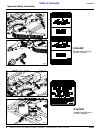
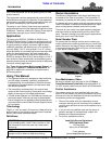
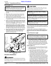
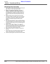
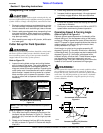
Wing Axle Assembly
!
WARNING!
Connect turnbuckle #3 to wing axle #2 before lowering wing.
Otherwise, personal injury or damage to the turnbuckle can
occur.
Refer to Figure 1-6
Wing axle locknuts are tightened for shipping purposes.
1. Loosen lock nuts (#1) slightly and rotate wing axles
(#2) to install turnbuckles (#3).
2. Remove cap screws and locknuts (#4).
3. Attach turnbuckles (#3) to the wing axles with
existing cap screws and lock nuts (#4).
4. Tighten locknut (#1) until snug. Do not overtighten.
Allow wing angle to pivot.
5. Tighten locknut (#4) to the correct torque.
Wing Axle - Turnbuckle Assembly
Figure 1-6
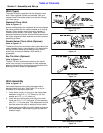
Tractor Hook-up to
Standard Clevis Hitch
!
DANGER!
A Crushing Hazard exist when hooking-up equipment to a
tractor. Do not allow anyone to stand between the tractor and
implement while backing-up to the implement. Do not operate
hydraulic 3-point lift controls while someone is directly
behind the tractor or near the implement.
NOTE: Do not tighten the hardware until assembly
is complete.
23703a
4
3
2
1
Turnbuckle(#3)
to be secured
between this
flange and the
one below.