


12
Section 1: Assembly and Set-up
PS25120 Primary Seeder 313-156M
8/21/06
Land Pride
Table of Contents
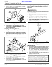
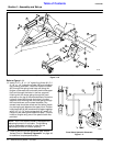
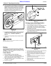
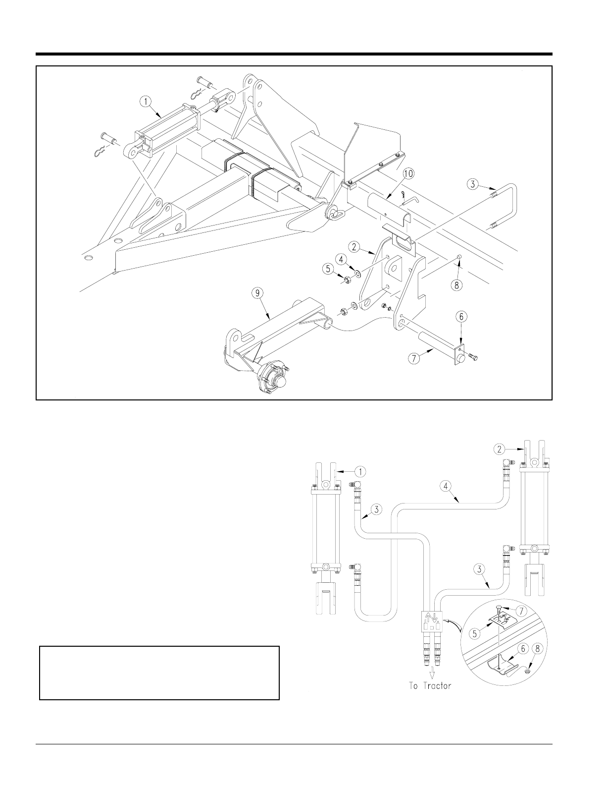
Cylinder, Wheel Bracket & Wheel Arm Assembly
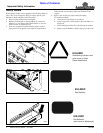
Figure 1-10
12740
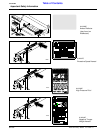
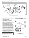
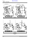
Refer to Figure 1-11:
13. Install 3 1/2” x 8” x 1 1/4” hydraulic cylinder (#1) 3 1/
4” x 8” x 1 1/4” hydraulic cylinder (#2) and complete
the plumbing as shown. Route the hydraulic hoses
(#3) through the spring hose loop and along the
tongue, underneath the turnbuckle, behind the upper
hitch and through the holes in the box supports,
finishing with the hoses going through the hose
retainers on the top of the wheel brackets. Route the
hydraulic hose (#4) through the holes in the box
supports, and finishing with the hose going through
the hose retainers on the wheel brackets. Any
excess hose should be coiled and tied with a plastic
tie, placing the coil between the upper hitch. Position
hose clamp (#5) & (#6) as shown and fasten together
with 5/16" x 1 1/4" long carriage bolt (#7) and 5/16"
flange nut (#8) adding the hoses from step 7. Secure
hoses to tongue using one of the plastic cable ties
provided.
14. Check to see all nuts are tightened. See Torque
Values Chart in “Section 9: Appendix” on page 48
for additional torque specifications.
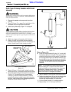
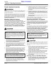
NOTE: Your Front Wheel Seeder is equipped with
rephasing hydraulic lift cylinders. The plumbing
must be assembled correctly in order for the
rephasing cylinders to function properly.
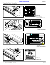
Front Wheel Hydraulic Schematic
Figure 1-11
15259