


11
Section 1: Assembly and Set-up
8/21/06
PS25120 Primary Seeder 313-156M
Land Pride
Table of Contents
Pull-Type Primary Seeder with Front
Wheels
!
WARNING
Serious injury or death couldresult fromescaping high pressure
hydraulic fluid. Use paper or cardboard, NOT BODY PARTS, to
check for suspected leaks.
1. Remove the seeder and components from their
crating.
2. Refer to Figure 1-3 on page 8 for installation of the
acremeter on to the right hand drive shaft.
3. Install spring hose loop, Figure 1-5 on page 8.
!
CAUTION
The Accumulator/Cylinder Package furnished with your front
wheel option is provided for your protection. Lack of or
improper installation may result in injury or in damage to your
seeder because of the negative tongue weight involved with the
front wheels.
4. Attach the tongue to the seeder with hitch pins.
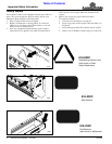
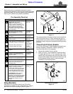
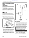
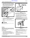
5. Refer to Figure 1-8 and attach the accumulator
bracket and accumulator to the rear of the tongue as
shown, fastening with hose clamps provided.
Accumulator Assembly
Figure 1-8
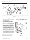
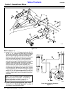
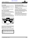
6. Refer to Figure 1-10 and install hydraulic cylinder
with single lug (#1) to tongue and top hitch as shown.
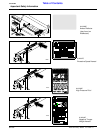
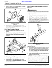
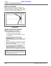
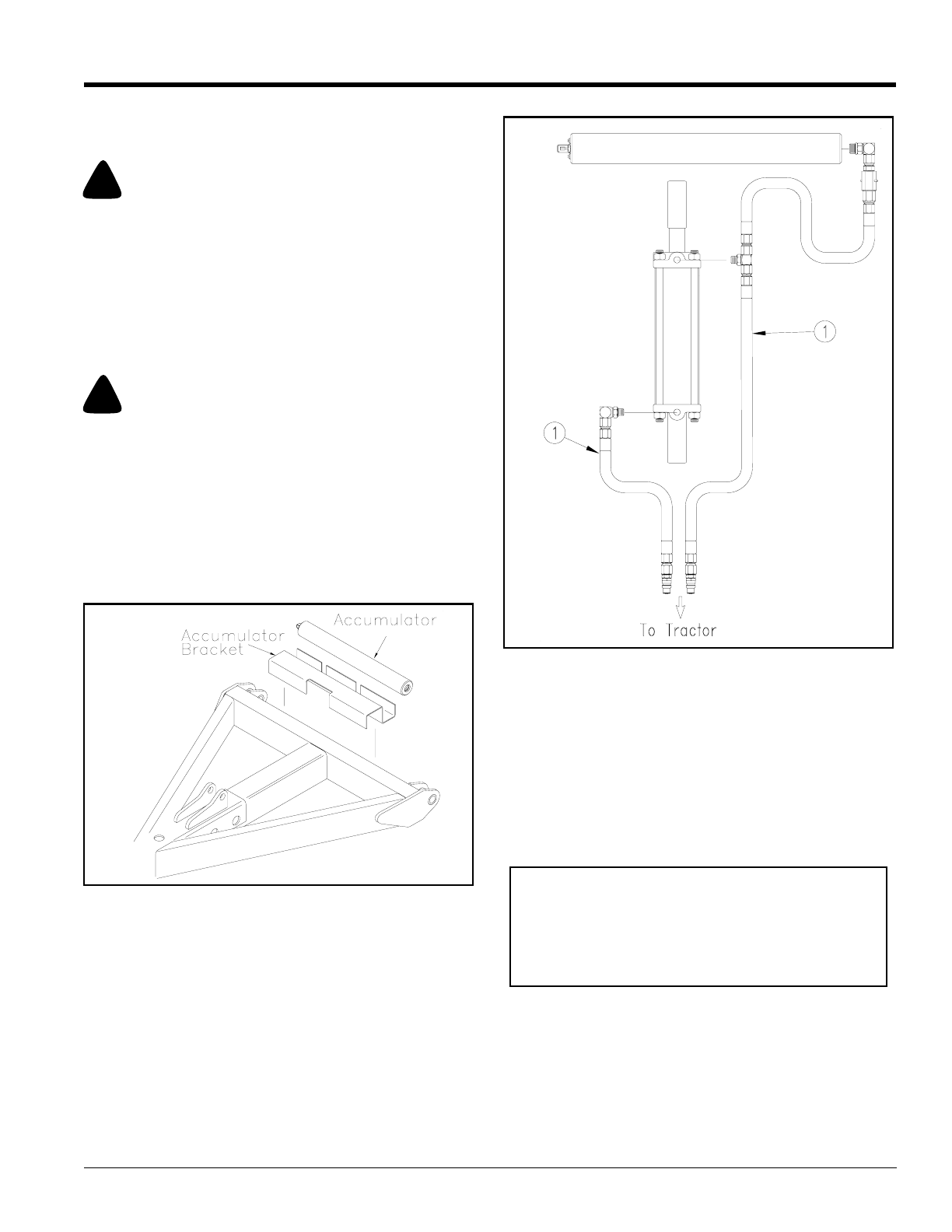
7. Complete the plumbing by following the schematic in
Figure 1-9. The plumbing must be assembled
correctly in order for the accumulator to function
properly. Route the hydraulic hoses (#1) along the
tongue. These hoses will be clamped together with
the wheel cylinder hoses in step 13.
12739
Accumulator Hydraulic Schematic
Figure 1-9
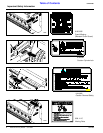
Refer to Figure 1-10:
8. Install the wheel bracket (#2) using 3/4" u-bolts (#3),
flat washers (#4) and nuts (#5). The wheel bracket
should be facing the front of the seeder. To determine
the correct positioning for the wheel brackets, note
the tab (#6) on the end of the wheel arm pivot (#7).
This tab should be toward the outside of the seeder,
as shown, so the wheel arm pivot can be easily
removed.
9. Remove wheel arm pivot shaft from wheel bracket.
10. Position the wheel arm (#9) so that the wheel points
toward the outside of the seeder with cylinder
bracket up. Replace wheel arm pivot shaft.
11. Pin the cylinder lock (#10) in storage position.
12. Repeat steps 9-11 for the right hand side.
15501
NOTE: The corresponding wheel brackets must be
positioned with the 1" hole over the front wheel
locating stub (#8) on the frame as shown for proper
distribution of seeder weight when in transport.
Locating the brackets at any other place on the
frame could result in damage to the seeder.