


18
Section 2: Operating
DM3705, DM3706, and DM3707 Series Disc Mowers 327-083M
9/15/06
Table of Contents
The cutting angle is defined as the angle the cutter bar is
to the tractor axle during operation. For example, cutter
bar angle would be down if cutting a declined surface
from a level surface and up if cutting and inclined
surface. Do not exceed a maximum of 35° up or down.
Damage to cutter gears, belt guard and drive belt may
occur.
!
DANGER
Do not use machine in rocky or stony conditions.
Extra care and precaution should be taken in rough or
debris-ridden fields. The following adjustments should
be made to the mower in these conditions to minimize
possibility of foreign objects being deflected by the
cutting blades.
1. Lengthen top 3-point center linkage to tilt angle of
cutter bar and raise height of cutter knives.
2. Reduce forward speed.
3. Check cutting blades to make sure they pivot after
hitting an obstruction.
!
CAUTION
Do not disengage PTO when engine is at full PTO rpm except
in emergency situations such as when hitting an obstruction.
When possible, always idle engine before disengaging PTO.
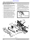
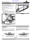
Safety Break-Away
The break-away latch allows cutter bar to swing back if
an obstruction is hit. If latch releases, stop tractor
immediately, idle engine and disengage PTO.
To reset cutter bar, back mower slowly and carefully until
break-away latch repositions. The factory setting of latch
is adapted to most working conditions.
Check cutter bar for any damage before resuming
operation.
If cutter bar continues to break away after resetting,
spring assembly pressure can be increased. In all cases
the length must not be less than 3 3/4” to 3 7/8” or safety
disengagement cannot function.
IMPORTANT: If an obstruction is hit, disengage
PTO, idle engine, shut off tractor, remove ignition
key and wait for all moving parts to come to a
complete stop. Inspect entire mower and repair any
damage before resuming operation.
IMPORTANT: To avoid personal injury, pick up all
rocks and other debris before mowing. Never
assume an area is clear, so enter a new area
carefully. Cut material higher the first time to allow
mower to clear unseen objects.
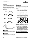
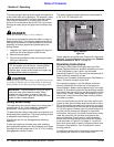
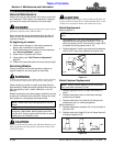
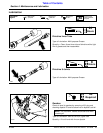
The stack of spring washers should be compressed to
3 3/4” to 3 7/8”. See figure 2-8
.
Spring Washers
figure 2-8
Spring washers can get flat over time and will need to be
replaced. To replace weak spring washers, see “Blade &
Belleville Washer Pt. No’s.” on page 22.
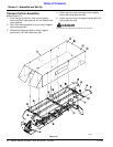
Operating Instructions
By now you should have thoroughly read your Disc
Mower Operator’s Manual, properly attached your Land
Pride Disc Mower to your tractor, and reviewed
Operating Check list. If you have not yet completed all of
these functions, please do so now.
Now that you’re properly briefed and your Disc Mower is
ready, it’s time to transport to the field.
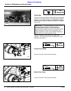
For transport purposes, your Disc Mower should be
securely locked with the cutter bar in the upright or
vertical position. Make sure the support leg is in the high
position. A “Slow Moving Vehicle” sign should be in place
and visible from the rear if you are using a public road or
right-of-way. Select a safe speed and transport to your
cutting site in such manner that faster moving vehicles
can pass you safely.
Once you have safely arrived at your field, position the
tractor on level ground. Make sure that no one is within
20 ft of the mower and lower the 3-point hitch to a point
where the inboard end of the cutter bar is approximately
12" off of the ground. Retract your lift cylinder and pull on
the latch cord to release the transport or road-latch
mechanism. Using your lift cylinder control lever, slowly
lower the cutter bar until the outer end touches the
ground. Adjust the 3-point hitch to “working position”
where the hitch level stop pin aligns with run indicator
arrow as shown in Figure 2-2 on page 13. Lock the 3-
point hitch control lever in place. Lock the hydraulic lever
of tractor in float position. Your Disc Mower is now in
working position.
Controlling or setting your cutting height is accomplished
by adjusting the “top link” on your 3-point hitch.
15092
3 3/4”
3 7/8”