


14
Section 2: Operating
DM3705, DM3706, and DM3707 Series Disc Mowers 327-083M
9/15/06
Table of Contents
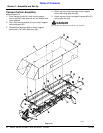
Driveline Installation
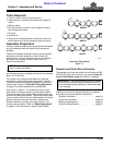
Refer to Figure 2-3 on page 14:
An additional driveline may be required if Disc Mower is
to be used on more than one tractor especially if a quick
hitch is used.
!
WARNING
Damaged drivelines can cause serious injury or death.
!
CAUTION
Tractor PTO shield and all Disc Mower guards must be in
place at all times during operation!
!
WARNING
Damaged drivelines can cause serious injury or death.
!
CAUTION
Always engage parking brake, shut off tractor and remove key
before dismounting from tractor.
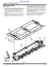
Checking Driveline Minimum Length
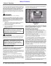
Refer to Figure 2-3:
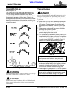
1. Start tractor and slowly engage 3-point to move
lower arms until Disc Mower’s gearbox shaft is
approximately level with tractor's PTO shaft.
2. Slide inner yoke of driveline over gearbox shaft and
secure in place.
3. Slide outer yoke of driveline over tractor PTO shaft
and secure with locking collar. Skip to step 5 on page
14 if driveline fits between tractor and Disc Mower.
4. The driveline will require shortening if it is too long to
fit between tractor and DiscMower. Shorten driveline
as follows:
IMPORTANT: Some tractors are equipped with
multi-speed PTO ranges. Be certain your tractor ‘s
PTO is set for 540 rpm.
IMPORTANT: Always check driveline minimum length
during initial setup, when connecting to a different
tractor and when alternating between using a quick
hitch and a standard 3-point hitch. More than one
driveline may be required to fit all applications.
IMPORTANT: It is necessary to aligning tractor’s
PTO shaft level with Disc Mower’s gearbox shaft
when checking driveline minimum length. Too long a
driveline can damage tractor, gearbox and driveline.
a. Raise or lower 3-point lower arms until Disc
Mower and tractor PTO shafts are approximately
level with each other. Securely block Disc Mower
frame in this position.
b. Set tractor in park, shut tractor engine off, set park
brake and remove switch key.
c. Pull driveline apart into two sections as shown in
Figure 2-3. Attach outer driveline universal joint to
tractor PTO shaft. Attach inner driveline universal
joint to gearbox shaft. Pull on each driveline
section to be sure universal joints are secured to
the shafts.
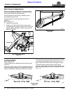
d. Hold driveline sections parallel to each other to
determine if they are too long. The inner and outer
shields on each section should endapproximately
1" short of reaching the universal joint shield on
the adjacent section (see “B” dimension). If they
are too long, measure 1" (“B” dimension) back
from universal joint shield and make a mark at this
location on inner and outer driveline shields.
e. Cut off inner shield at mark (“X” dimension). Cut
same amount off inner shaft (“X1” dimension).
Repeat cut off procedure (“Y”&“Y1” dimensions)
to cut outer driveline half.
f. Remove all burrs and cuttings.
Figure 2-3
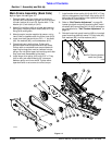
5. Apply multi-purpose grease to the inside of outer
driveline shaft and reassemble the two shafts.
6. Attach inner driveline yoke to mower gearbox input
shaft.
7. Attach outer driveline yoke to tractor's PTO shaft.
8. The driveline should now be moved back and forth to
insure that both ends are secured to the tractor and
Disc Mower PTO shafts. Reattach any end that is
loose.
22227