


13
Section 2: Operating
9/15/06
DM3705, DM3706, and DM3707 Series Disc Mowers 327-083M
Table of Contents
Section 2: Operating
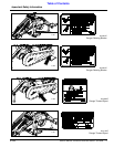
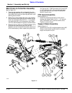
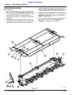
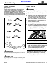
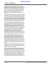
3-point Pin Set-up
Refer to Figure 2-1:
The 3-point pins in the mower may be arranged four
different ways to accommodate different tractor sizes.
The first 3-point offset arrangement shown below
positions the first cutter blade closest to the tractor. Each
arrangement thereafter is further away. Select a pin
arrangement that will allow the first cutter blade to extend
beyond the tractor’s back right wheel far enough to cut a
full mower swath without the tractor’s wheel running over
material being cut.
Figure 2-1
!
WARNING
Be sure driveline is properly connected. A loose yoke could slip
and cause personal injury or damage to the mower.
!
CAUTION
By their nature rotary disc throws debris and although curtain
stops most of it,some debris is still thrown towardsthe operator.
Select a tractor with a cab or shield to protect operator from
thrown debris.
20774
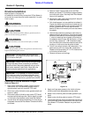
Tractor Hook-up
!
DANGER
Refer to Figure 1-2 on page 9. Do not connect or disconnect
mower to tractor with upper spring (#9) connected to pin (B).
The upper spring pulls on the 3-point main frame and will
quickly turn the main frame upon removing one of the tractor’s
3-point arms.
6. Back tractor up to the disc mower so that the lower
3-point arms are aligned with lower lift pins of the
disc mower. Connect to lower 3-point arms with
proper attaching hardware. Connect 3-point upper
link.
7. Raise mower cutter bar off the ground slightly by
actuating the hydraulic cylinder.
8. Adjust length of tractor’s two sway link arms to
prevent swaying from side to side.
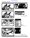
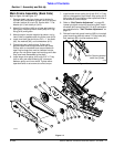
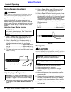
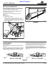
9. The check chain is used when tractor’s 3-point hitch
is unable to hold the mower in the working position.
Attach check chain to top 3-point center link of tractor
making sure that hitch stop pin is aligned with run
indicator decal #838-524C as shown in Figure 2-2
below. This is known as the working position.
.
Figure 2-2
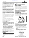
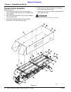
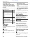
10. With mower attached, park tractor on a flat level
surface and adjust lower 3-point draft arms to level
mower. Verify levelness by measuring distance from
center of connecting pins to floor. This distance
should be the same for both connecting pins.
11. Raise support leg and position it in the high position.
12. Add ballast weights to front of tractor as needed to
counter balance mower weight.
21021
IMPORTANT: Mower must be leveled at the 3-point
arms for mower and hitch level stop pin to work
properly.
IMPORTANT: The tractor must have enough
counter weight on the front to transport over rough
terrain without front wheels lifting off the ground.