


16
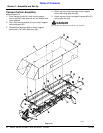
Section 2: Operating
DM3705, DM3706, and DM3707 Series Disc Mowers 327-083M
9/15/06
Table of Contents
Spring Tension Adjustment
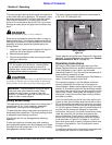
!
DANGER
Before making any adjustments to this implement, disengage
PTO, shut off tractor, remove ignition key and wait for all
moving parts to stop. Disconnect PTO driveline.
There are two springs on the mower. The lower spring
attached to the reach arm adjusts response time
between when 3-point arms raise and when cutter bar
starts to raise. The upper spring attached to the curtain
support arm adjusts ability of cutter bar to float on the
ground.
Adjusting Lower Spring Tension
1. Refer to Figure 2-2 on page 13. Position 3-point
arms so that hitch level stop pin aligns with run
indicator arrow (decal 838-524C).
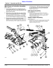
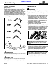
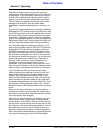
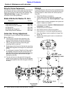
2. Refer to Figure 2-6 below. Adjust accordingly by
turning handle until “X” dimension is equal to the
dimension represented below for your mower.
DM3705. . . . . . . . . . . . . . . . X = Approximately 2 3/4”
Dm3706. . . . . . . . . . . . . . . . X = Approximately 2 1/8”
DM3707. . . . . . . . . . . . . . . . X = Approximately 1 1/2”
3. The lower spring may need readjusting after several
hours of running.
Figure 2-6
Adjusting Upper Spring Tension
1. Attach upper spring slotted arm to mower as outlined
in the section titled “Upper Spring Connection” on
page 15.
IMPORTANT: The mower must be leveled for lower
spring tension to work properly. See Tractor Hook-
up paragraph 5 on page 13 for instructions on
leveling.
21039
X”
Cylinder Spring Mount
Handle
IMPORTANT: The mower must be leveled for upper
spring tension to work properly. See Tractor Hook-up
paragraph 5 on page 13 for instructions on leveling.
2. Refer to Figure 2-2 on page 13. Position 3-point
arms so that hitch level stop pin aligns with run
indicator arrow (decal 838-524C).
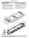
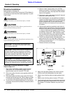
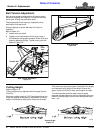
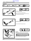
3. Refer to Figure 2-7 below. Retract hydraulic cylinder
to release upper spring tension and loosen jam nut.
Adjust spring by turning it until “X” dimension is equal
to the dimension represented below for your mower.
This dimension should adjust pick-up weight of
mower end to approximately 100 lbs when hydraulic
cylinder is extended to field operating position.
Retighten jam nut.
DM3705 . . . . . . . . . . . . . . . . . . .X = Approximately 3”
Dm3706 . . . . . . . . . . . . . . . . . . .X = Approximately 2”
DM3707 . . . . . . . . . . . . . . . . . . .X = Approximately 1”
Figure 2-7
Transporting
!
CAUTION
When traveling on public roads at night or during the day, use
accessory lights and devices for adequate warning to operators
of other vehicles. Comply with all federal, state and local laws.
1. Raise cutter bar so it is in a vertical position.
2. Make sure transport lock engages.
3. Make sure support leg is secured in the high
position.
4. Approach disc mower from rear making sure Slow
Moving Vehicle emblem on tractor is visible to
oncoming traffic.
5. Select a safe ground speed when transporting from
one area to another. When traveling on roadways,
transport in such a way that faster moving vehicles
may pass you safely.
6. When traveling over rough or hilly terrain, shift tractor
to a lower gear.
X”
21040
Jam Nut
IMPORTANT: Always disengage tractor’s PTO
before raising mower to transport position.
NOTE: When raising mower to transport position be
sure that PTO shaft does not contact tractor or
mower.