


9
Section 1: Assembly and Set-Up
9/15/06
DM3705, DM3706, and DM3707 Series Disc Mowers 327-083M
Table of Contents
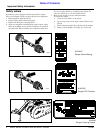
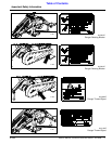
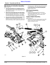
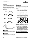
Main Frame to Cutter Bar Assembly
Refer to Figure 1-2:
4. The cutter bar gearbox (#1) is shipped with nylon
bushings (#2) mounted on both sides of gearbox thru
input shaft. Slide reach arm pivot lug (#3) over nylon
bushing (#2) as shown.
5. Slide pivot lug arm bracket (#4) over nylon bushing
(#2) as shown. Attach pivot lug arm bracket (#4) to
reach arm weldment (#3) with 3/4” x 1 1/4” grade 5
hex head bolts (#5), and Lockwashers (#6). Apply
LocTite to bolt threads and tighten to proper torque.
6. Remove linch pin (#13) and 1” USS flat washer (#12)
to disconnect upper spring (#9) from pin (B).
Reattach linch pin (#13) and flat washer (#12) to pin
(B) for safe keeping. Attach upper spring (#9) to pin
(A). Secure with 1” SAE flat washer (#10) and 5/32”
x 1 3/4” cotter pin (#11). Do not reconnect upper
spring to pin (B) until after mower is attached to
tractor’s 3-point arms.
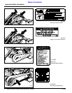
PTO Guard Assembly
Refer to Figure 1-2:
1. Attach bell shaped guard (#15) to main frame
housing with spacer (#14), 5/16” x 1 1/4” hex bolt
(#16), lockwasher (#17), and flat washer (#18).
Tighten to correct torque.
Support Stand Assembly
Refer to Figure 1-2:
1. Remove linch pin (#7) to adjust support stand (#8).
Raise or lower stand in guide tube to a suitable
height and replace linch pin.
21022
Figure 1-2