


15
Section 2: Operating
9/15/06
DM3705, DM3706, and DM3707 Series Disc Mowers 327-083M
Table of Contents
9. Hook one of the driveline safety chains in a hole on
the outer driveline yoke shield and the opposite end
to the tractor to restrict outer shield rotation.
10. Hook second driveline safety chain in a hole on the
inner driveline yoke shield and the opposite end to
the Disc Mower to restrict inner shield rotation.
11. Start tractor and raise Disc Mower just enough to
remove blocks used to support Disc Mower frame in
step 4a on page 14.
12. Slowly engage tractor’s hydraulic 3-point to lower
Disc Mower. Check for sufficient drawbar clearance.
Move drawbar ahead, aside or remove if required.
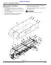
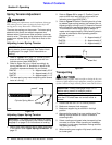
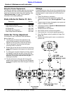
Rope Hook-up
Refer to Figure 2-4:
Two ropes are provided so that the operator does not
need to get off the tractor to unlock cutter bar in the up
position after transporting. Thread both ropes through
the guide loop (#1) located on top of the main frame and
tie free ends to tractor within reach of operator.
Figure 2-4
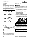
Transport Latch Operation
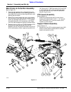
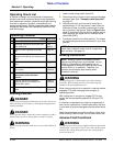
Refer to Figure 2-5:
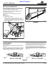
Change mower from field position to transport position by
pulling on field run latch rope and retracting hydraulic
cylinder until transport latch (#2) engages.
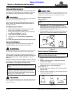
Change mower from transport position to field position by
retracting hydraulic cylinder, pulling on transport latch
rope (#2), and then extending hydraulic cylinder until
cutter bar reaches field running position.
IMPORTANT: Two small chains are supplied with
the driveline. These chains must be attached to
outer and inner driveline yoke shields and to the
cutter deck and tractor to restrict driveline shields
from rotating.
21020
Figure 2-5
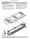
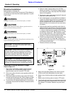
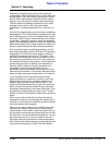
Upper Spring Connection
Refer to Figure 1-2 on page 9:
!
DANGER
Do not connect or disconnect mower to tractor with upper
spring (#9) connected to pin (B). The upper spring pulls on
3-point main frame and will quickly turn main frame upon
removing one of the tractor’s 3-point arms.
The upper spring (#9) should be connected to pin (B)
after mower has been hooked-up to a tractor and
disconnected from pin (B) before unhooking mower from
a tractor.
After Hooking-up Mower to Tractor
Attach upper spring (#9) by retracting hydraulic cylinder
until spring’s slotted bar is inserted over pin (B). Secure
upper spring to pin (B) with flat washer (#12) and linch
pin (#13).
Before Unhooking Mower From Tractor
Disconnect upper spring (#9) by retracting hydraulic
cylinder until upper spring slotted bar can be removed
from pin (B). Remove flat washer (#12), linch pin (#13),
and slotted bar from pin (B). Return washer and linch pin
to pin (B) for storage.
21033