


11
Section 1: Assembly and Set-Up
9/15/06
DM3705, DM3706, and DM3707 Series Disc Mowers 327-083M
Table of Contents
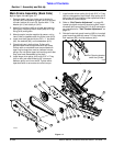
Main Frame Assembly (Back Side)
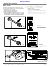
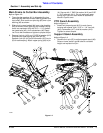
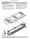
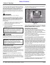
Refer to Figure 1-4 and Figure 1-5:
1. Remove plastic cap from lower port in hydraulic
cylinder (#15) and extend cylinder (#15) to connect
cylinder rod eye (A) to pin (B). Secure with 1” Flat
washer (#11) and cotter pin (#12).
2. Attach O-ring fitting (#18) to cylinder port opening
and tighten. Attach hydraulic hose (#19) to O-ring
fitting (#18) and tighten.
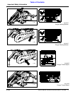
3. Attach coupler (coupler supplied by owner, not by
Land Pride) to opposite end of cylinder hose (#19).
4. Install inner belt guard with four 3/8” x 1” hex bolts
(#6), flat washers (#9), and lockwashers (#10).
5. Check hub type in both pulleys. Pulleys with
standard bore hubs are provided with set crews.
Pulleys with an oversized bore are provided with
taper lock busings that must be inserted into the
pulleys. Do not tighten taper lock bushings until after
they have been assembled to the shaft.
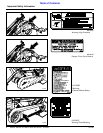
6. Install larger drive pulley (#13) with 5/16” x 2” key
(#4) to main jack shaft allowing 3/8” clearance
between pulley and inner shield. Tighten either
taperlock bolts or set screws to correct torque.
7. Install smaller driven pulley (#14) with 5/16” x 2” key
(#4) to cutter gearbox input shaft. Align pulley (#14)
with pulley (#13) and tighten either taperlock bolts or
set screws to correct torque.
8. Refer to “Belt Tension Adjustment” on page 20.
Loosen pivot bolt and pulley tensioning bolt. Install
drive belt (#16) over pulleys (#13, & #14) and tension
per instructions for ““Belt Tension Adjustment” on
page 20”.
9. Reinstall outer belt guard housing (#20) to inner belt
guard mounting plate with seven 1/4” hex bolts (#5),
lock washers (#9), and flat washers (#10).
Figure 1-5
21052
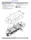
Port Opening located
under the cylinder
21024
Figure 1-4