


28
Section 5: Maintenance and Lubrication
AFM4522 All Flex Grooming Mower 315-360M
11/14/08
Land Pride
Table of Contents
Driveline Protection
Mower drive components are protected from shock loads
by a two plate friction clutch. The clutch should slip
during operation to protect the mower from excessive
loads.
Friction clutches should be “run-in” prior to initial
operation and after long periods of inactivity. To prevent
driveline and gearbox damage, repeat “Run-In”
instructions at the beginning of each season and when
moisture and/or condensation seizes the inner friction
plates.
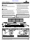
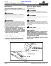
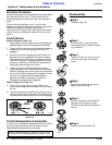
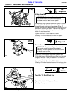
Clutch Run-In
Refer to Figure 5-9 (View - A):
1. Using a pencil or other marker, scribe a line across the
exposed edges of the clutch plates and friction disks.
2. Tighten all 4 nuts uniformly until the spring load is low
enough that the clutch slips freely with the PTO
engaged.
3. Start the tractor and engage driveline drive for 2-3
seconds to permit slippage of the clutch surfaces.
Disengage the driveline, then re-engage a second
time for 2-3 seconds. Disengage driveline, shut off
tractor and remove key. Wait for all components to
stop before dismounting from tractor.
4. Inspect the clutch and ensure that the scribed
markings made on the clutch plates have changed
position. Slippage has not occurred if any two marks
on the friction disk and plate are still aligned. A clutch
that has not slipped must be disassembled to
separate the friction disk plates. See Clutch
Disassembly & Assembly on page 28.
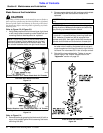
Refer to Figure 5-9 (View - B):
5. Turn all 4 nuts fully back if no two marks on the
friction disk and plate are still aligned. Clutch is ready
for use.
6. The clutch should be checked during the first hour of
cutting and periodically each week. An additional set
of scribe marks can be added to check for slippage.
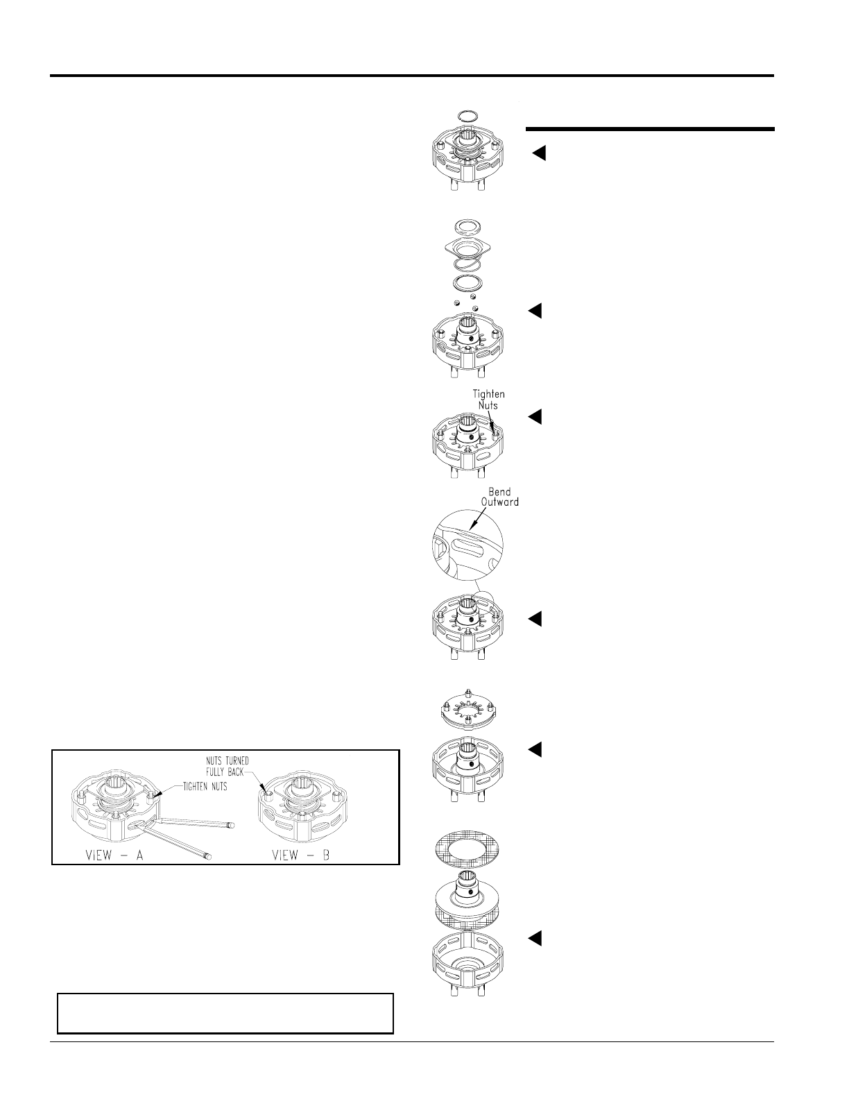
Clutch Run-In
Figure 5-9
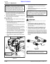
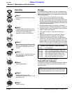
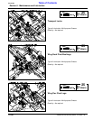
Clutch Disassembly & Assembly
If “Clutch Run-In” procedure indicated that one or more of
the friction disks did not slip, then the clutch must be
disassembled to separate the friction disks.
22171
NOTE: Before proceeding, secure the clutch firmly
in a vise or other clamping device to prevent injury.
10435
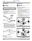
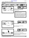
Step 2
Remove backup ring, lock collar,
compression spring, bottom backup
ring, and balls.
Step 3
Tighten the four hex nuts uniformly
until the clutch pack and hub are
loose.
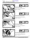
Step 4
Bend all four retaining lugs out on
edge of clutch housing.
Step 5
Remove thrust plate with Belleville
Springs and lug rings to access
friction discs and hubfor inspection or
service.
Disassembly
Step 1
Remove snap ring.
Step 6
Inspect friction discs and hub.