


23
Section 3: Adjustments
11/14/08
AFM4522 All Flex Grooming Mower 315-360M
Land Pride
Table of Contents
8. Take measurements from the same location on all
three decks to make sure they are at the same
cutting heights.
9. Additional fine tuning adjustments may be needed
after a test mowing run.
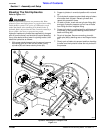
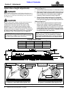
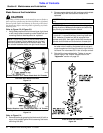
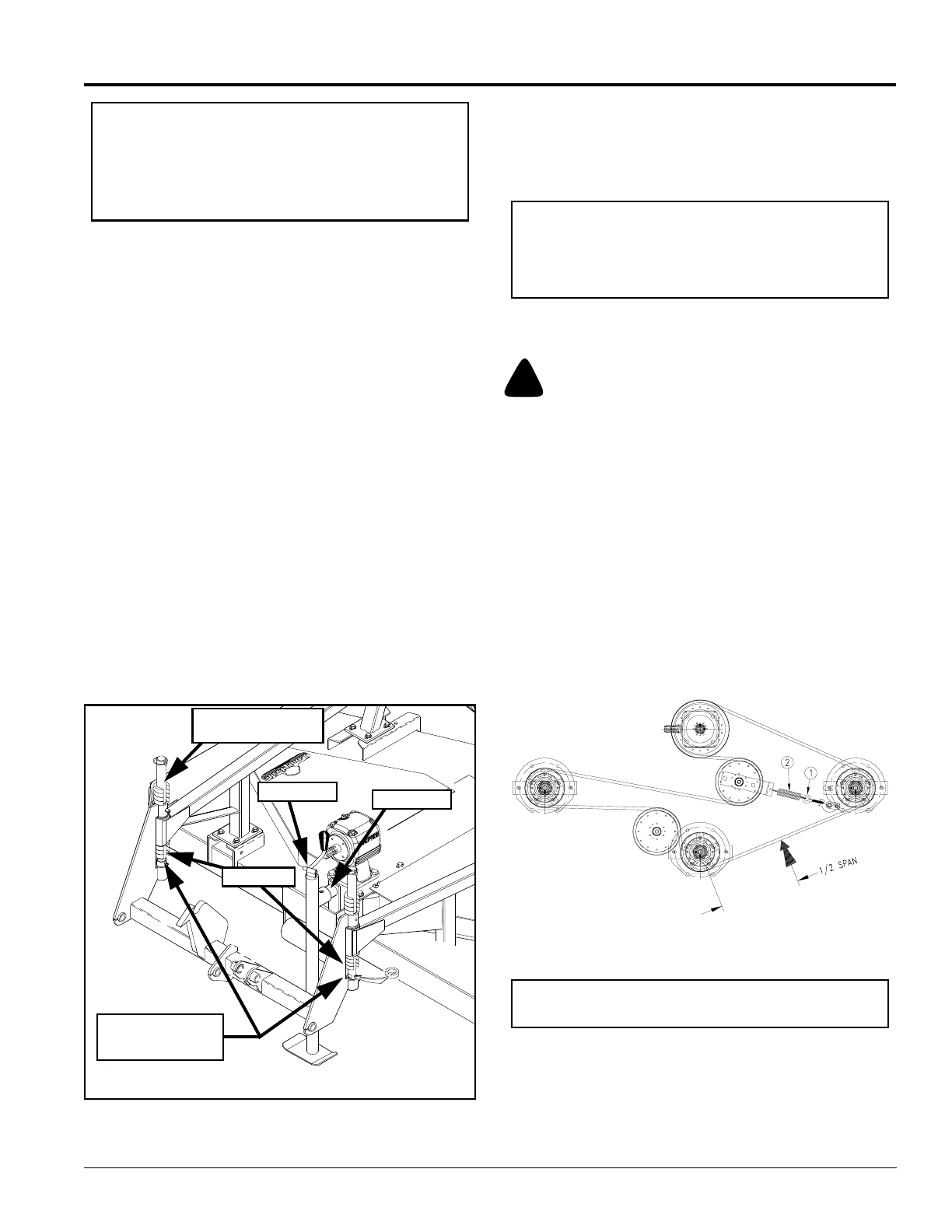
Belt Tension
Refer to Figure 3-4:
!
CAUTION
Belt drive system under spring tension; use care to avoid
bodily harm!
1. To check tension, apply force at arrow A with a
tension tester until the belt is deflected 1/4”. The
force required to get this deflection should range
from 7 to 10 lbs.
2. Adjust belt tension by adjusting eyebolt (#1) until
correct tension is achieved. This adjustment will
increase or decrease the tension on spring (#2).
3. Excessive tension on the belt may lead to premature
failure of belt and drive components. Also excessive
tension may become a safety hazard to the operator
and bystanders. Not enough tension on the belt may
lead to premature failure of the belt due to excessive
slipping.
Belt Tension
Figure 3-4
IMPORTANT: Slide-on spacers for the front of the
center deck are all 1/2” long, so double the quantity
of the spacers vs. the spacers on the gauge wheels
(i.e., two 1” spacers used on gauge wheel vs. four
spacers on the front center deck adjustment).
15583
IMPORTANT: Belt tension should be checked on new
belts after approximately 20 hours of operation.
5. After making height adjustments, always replace
linch pins by inserting them into the gauge wheel
spindle pin holes from the front to keep from loosing
the pins and gauge wheels.
6. Lower mower decks to the field position making sure
all fold cylinders are fully extended.
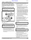
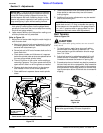
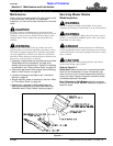
Refer to Figure 3-3:
7. Adjust front of center deck height to match height at
rear of center deck:
a. Attach jack stand to jack mount located in front of
the center gearbox channel. Make sure stand is
secured with attachment pin.
b. Screw jack out to lift front of mower deck and in to
lower deck front.
c. Place same number and thickness of c-spacers
below the spindle tube as what was placed below
the rear gauge wheel spindle tubes.
d. There is a groove in the carrier rod for adding or
removing c-spacers. Turn the c-spacer so that the
open end will slide in or off the groove as needed.
e. Remove jack stand and return it to the storage
tube located in front of the divider gearbox.
f. Place additional c-spacers above metal spindle
tubes.
Jack Mounting Tube
Figure 3-3
IMPORTANT: Linch pins should always be inserted
into the gauge wheel spindle pin holes from the front
so that the locking clasp is flipped shut over the
spindle towards the back. Attaching the pin in this
manner will prevent vegetation from catching on the
clasp and flipping it open while traveling forward.
26856
Some mower items not shown for clarity
Additional
C-Spacers on Top
Jack Mount
Screw Jack
Groove on Rod
to Add or Remove
C-Spacers
C-Spacers