


11
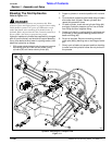
Section 1: Assembly and Setup
11/14/08
AFM4522 All Flex Grooming Mower 315-360M
Land Pride
Table of Contents
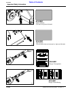
Section 1: Assembly and Setup
Tractor Requirements
Tractor horsepower should be within the range noted
below. Tractors outside the horsepower range must not
be used.
Horsepower Rating . . . . . . . . . . . . . . . . . . 65-100 HP
Rear PTO Shaft Type. . . . . . . . . . . . . .1 3/8”-6 Spline
Rear PTO Speed . . . . . . . . . . . . . . . . . . . . 540 RPM
Hitch Type . . . . . . . . . . . . . . . . . . . . . . . . . . Draw Bar
Hydraulic Outlets . . . . . . . . . . . . . .One Duplex Outlet
Tractor Weight . . . . . . . . . .See Important Note Below
Hardware Torque Information
When tightening hardware, refer to “Torque Values
Chart” on page 39 to determine standard torque values.
Refer to "Additional Torque Values" at the bottom of the
chart for exceptions to the standard torque values.
Dealer Preparations
This mower has been partially assembled at the factory.
some additional preparations will be necessary to finish
assembling the mower and to attach it to the customer’s
tractor. Ensure that the intended tractor conforms to the
requirements stated under the heading “Tractor
Requirements”.
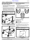
IMPORTANT: Ballast may need to be added to your
tractor to maintain steering control. Refer to your
tractor’s operator manual to determine if additional
ballast is needed. This mower has a positive
transport tongue weight of approximately 540 lbs. on
the AFM4214 and 580 lbs. on the AFM4216.
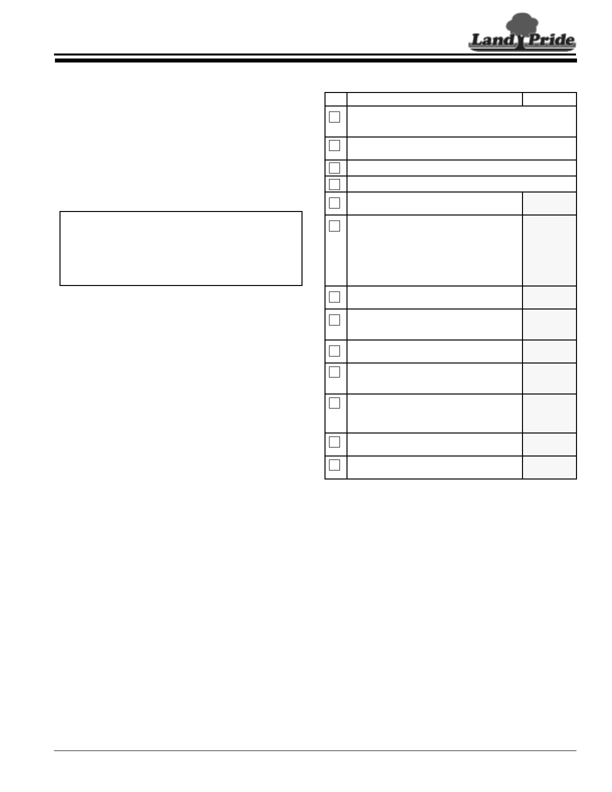
Pre-Assembly Checklist
Check Reference
Make sure miscellaneous assembly tools are on hand: Hammer,
tape measure, hacksaw,assortment of wrenches & sockets, 3/8"
drill, drill bits and spirit level.
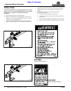
Have a forklift or hoist with properly sized chains and safety
stands on hand capable of lifting 2500 lbs.
Have a minimum of two people available during assembly.
Check to see if auxiliary tractor weights are needed.
Make sure all major components and loose parts
are shipped with the machine.
Operator’s
Manual
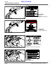
Double check to make sure all fasteners & pins
are installed in the correct location. Refer to the
Parts Manual if unsure.
NOTE: All assembled hardware from the factory
has been installed in the correct location.
Remember location of a part or fastener if
removed during assembly. Keep parts separated.
Operator’s
Manual
Make sure working parts move freely, bolts are
tight & cotter pins are spread.
Operator’s
Manual
80-90 EP Gear Lube must be added to the
gearbox & motor as indicated in the
“Maintenance & Lubrication”.
Section 5
Page 30
Make sure all drive chains are properly tension
and aligned.
Operator’s
Manual
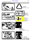
Make sure all safety labels are correctly located
and legible. Replace if damaged.
Important
Safety
Information
Make sure all red and amber reflectors are
correctly located and visible when machine is in
transport position.
Important
Safety
Information
Page 1
Make sure all tires are inflated to the specified
psi air pressure.
Section 8
Page 39
Make sure all wheel bolts and axle nuts are
tightened to the specified torque.
Section 8
Page 39