


12
Section 1: Assembly and Setup
AFM4522 All Flex Grooming Mower 315-360M
11/14/08
Land Pride
Table of Contents
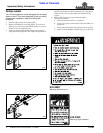
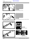
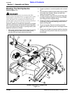
Deck Gauge Wheel Assembly
Refer to Figure 1-1 and Figure 1-2:
1. Remove mower decks (3 each) from their shipping
crates. Set each deck on a working stand capable of
supporting the decks high enough to install gauge
wheel assemblies (#1).
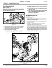
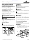
2. Assemble gauge wheel yoke assemblies (#1) to the
decks with hardware indicated. 6 gauge wheel
assemblies are castered yoke with round shafts and
4 assemblies are non-castered yoke with square
shafts. See Figure 1-1 and Figure 1-2 for correct
location of castered and non-castered assemblies.
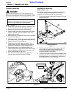
Center Deck Gauge Wheel Assembly
Figure 1-1
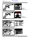
Wing Deck Gauge Wheel Assembly
Figure 1-2
IMPORTANT: Be sure to position equal size and
amount of spacers under each spindle. See Center
Deck Height Adjustments in the “Adjustments”
section on page 22.
15577
15613
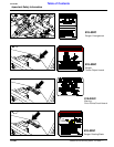
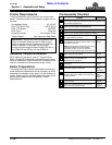
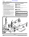
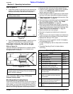
PTO To Drawbar Set-Up
Refer to Figure 1-3:
3. Remove mower decks from their working stands and
position them on a level surface in the arrangement
shown. Left and right wing gearbox input shafts
should point towards each other.
Deck Location
Figure 1-3
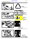
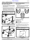
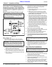
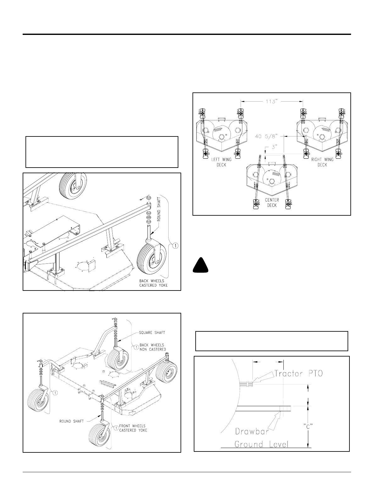
Drawbar Positioning
Refer to Figure 1-4:
!
CAUTION
Do not over speed PTO or machine damage may result. This
mower is designed to be used with a tractor using a rear
540 rpm PTO drive.
The 14” distances between center of drawbar hitch pin
hole to end of tractor PTO shaft and 8” distance from top
of drawbar hitch to center of PTO shaft must be
maintained.
PTO to Drawbar Distances
Figure 1-4
15584
IMPORTANT: PTO damage may occur if 14" & 8"
distances are not properly maintained.
22273
14"
8"