


23
Section 3: Adjustments
1/12/09
Z44 & Z52 (S/N 526171 & Above) Zero Turning Radius Mowers Riding Mowers Accu-Z Razor
®
357-187M
Land Pride
Table of Contents
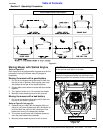
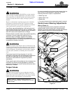
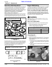
Deck Drive Belt Adjustment
The spindle belt remains in constant tension by means of
a spring tensioned idler. The spring tension should be
adjusted so that the belt does not slip under normal
operating load conditions and may require readjusting as
the belt stretches and wears. The belt should be
replaced if it is excessively worn or damaged.
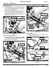
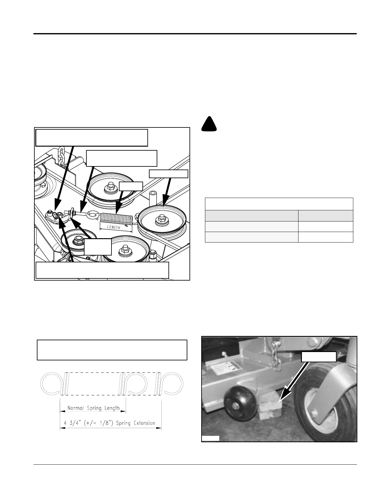
Refer to Figure 3-6 and Figure 3-7:
Check spring length to verify if belt is tensioned correctly.
Installed spring length should be 4 3/4" +or- 1/8". Vary
the spring length by adjusting the length of the eye bolt.
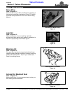
Drive Belt Adjustment
Figure 3-6
Excessive belt tension may lead to premature damage of
belt and drive components and is also a safety hazard to
the operator and bystanders. Not enough belt tension
may also lead to premature belt damage due to
excessive belt slippage.
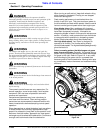
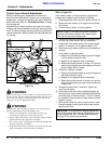
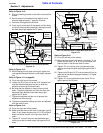
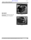
Deck Drive Belt Adjustment
Figure 3-7
23628
Eye Bolt (Adjust Length
To Vary Spring Tension)
Hitch Pin
Remove Before Releasing Belt Tension
Tension Idler
Spring
Over-Center-Release Bolt
(Turn Counterclockwise to Release Belt Tension)
Anchor
Bracket
IMPORTANT: Do not over tension the spring to
compensate for a badly worn belt or pulley.
24562
Engine RPM Setting
The Razor is designed so that the engine will run at 3600
rpm static pump load only. At this speed the hydraulic
pumps are running at their maximum rated speed.
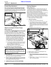
Deck Leveling & Height Adjustment
The mower deck has three areas that may need to be
checked and adjusted periodically. Before considering
any mower deck leveling adjustments, check that the tire
air pressure is within the specified range.
!
WARNING
Stop engine. Make sure blade engagement switch is in the
down (OFF) position. Place control levers in park position
before leaving machine.
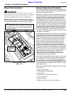
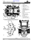
Deck Level Adjustments
Leveling the deck must be done in the following order:
1. Check tire pressures to make certain they are
properly inflated before leveling deck.
2. Park the unit on a flat surface.
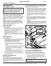
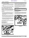
Refer to Figure 3-8:
3. Raise deck fully up.
4. Position the blade cutting height at 3 1/4” by placing
3" high deck support blocks under the deck edge in
three locations:
a. Place two of the 3" support blocks under the deck
front edge in-line with the far left and far right blade
spindles.
b. Center the third 3" support block under the deck
back edge.
Blocking up Deck
Figure 3-8
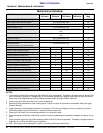
Tire Inflation Chart
Tire Inflation PSI
Drive Wheels 8-12
Caster Wheels 8-12
Blocks
23800