


21
Section 3: Adjustments
1/12/09
Z44 & Z52 (S/N 526171 & Above) Zero Turning Radius Mowers Riding Mowers Accu-Z Razor
®
357-187M
Land Pride
Table of Contents
Forward Stop Adjustment
The control lever stops are designed to do two things:
First, and most important, they must keep the pumps
from bottoming out internally. Second, the stops may be
adjusted to help drive straight when the control levers are
pushed forward against the stops.
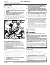
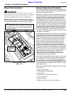
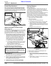
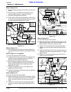
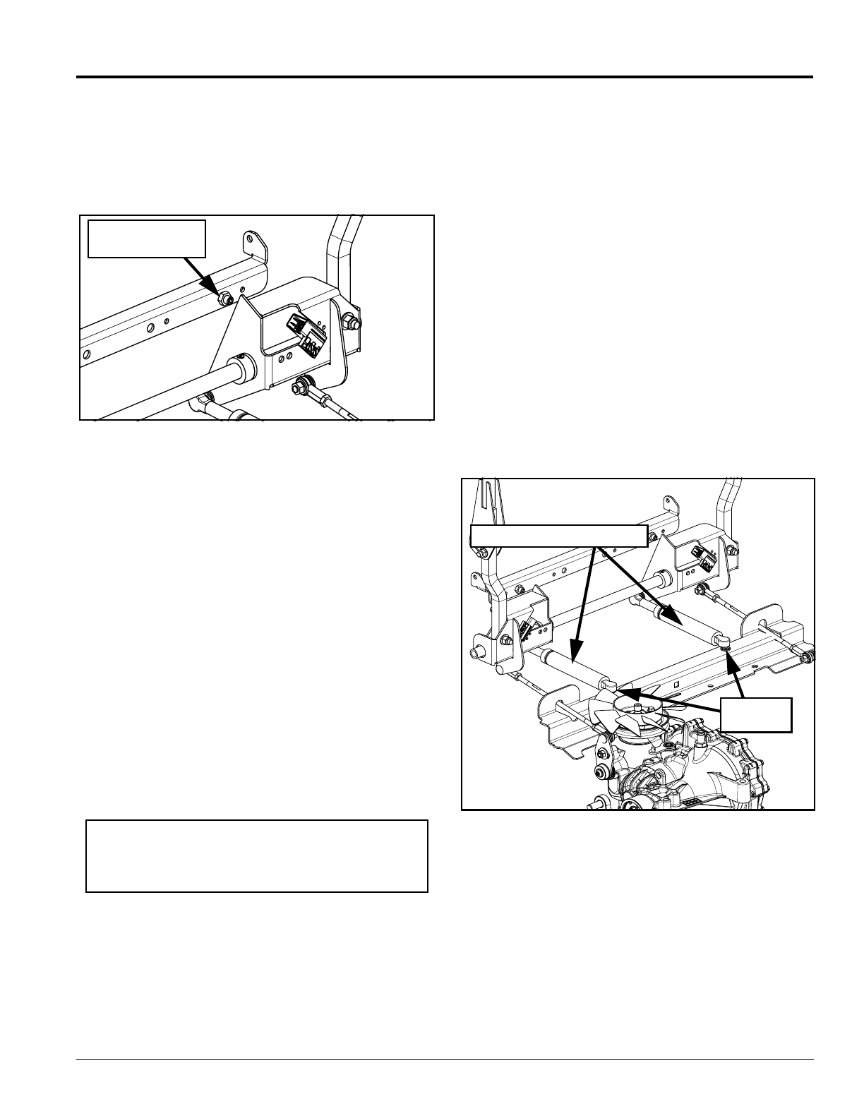
Steering Control Stop (Right side Shown)
Figure 3-3
Adjust Lever Stops to Protect Pumps
Refer to Figure 3-3:
This adjustment should be made first and must be made
with mower engine NOT RUNNING. Check one side at a
time to make sure each control lever is against the
adjustable stop before the pump bottoms out internally.
1. Raise the seat up and gently and slowly move one of
the control levers forward and feel if there is some
resistance on the lever before the control lever hits
the stop. If you sense the pump linkage rod is
stopping forward motion before the control lever
comes against the stop, then do the following:
a. Loosen the jam nut for that adjustable stop.
b. Turn stop (hex socket set screw) out until control
lever is stopped by the set screw slightly before
the pump linkage rod bottoms out.
c. When adjustment is correct, tighten jam nut.
2. Repeat step 1 for the other control lever.
Adjust Lever Stops to Drive Straight
Refer to Figure 3-3:
1. Determine which drive tire is rotating too fast when
both control levers are against the stops.
2. Stop the mower and loosen the jam nut on the side
which is rotating too fast. Back the stop (set screw)
out to stop the control lever sooner.
3. Tighten the jam nut on the stop and test again.
4. Repeat this procedure until unit drives straight.
24910
Control Lever
Adjustable Stops
NOTE: Variables such as oil temperature, pump
efficiency, motor efficiency, tire pressure, etc., may
effect the consistency to drive straight while pressing
the control levers against the stops.
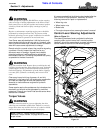
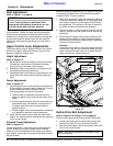
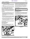
Steering Dampener
Refer to Figure 3-4:
The steering dampeners, located under the seat, are
incorporated into the unit to provide some resistance
when control levers are moved forward or rearward and
return levers to neutral when backing up.
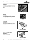
Make sure steering dampeners are adjusted properly by
moving control levers to the reverse position and
releasing them. If control levers return to neutral position,
they are working correctly. Adjust dampeners if they do
not return to neutral. Adjusted as follows:
1. Place control lever in neutral position.
2. Adjust left dampener:
a. Loosen nut on the left rear ball stud.
b. Pull dampener spring housing, to the rear, past
the point that the internal spring is engaged.
c. Release dampener spring housing and allow the
internal spring to bring the housing back to neutral
position.
d. Retighten left rear ball stud nut.
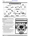
Steering Dampener
Figure 3-4
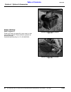
3. Repeat step 2 to adjust the right dampener rod.
4. Check steering dampeners:
a. Move the control levers to reverse position and
release. The control levers should return to neutral
position.
b. Repeat steps 1 through 4 if control levers do not
return to neutral position.
Rear
Ball Studs
Dampener Spring Housings
24910