


20
Section 3: Adjustments
Z44 & Z52 (S/N 526171 & Above) Zero Turning Radius Mowers Riding Mowers Accu-Z Razor
®
357-187M
1/12/09
Land Pride
Table of Contents
Control Lever Neutral Adjustment
Before considering any adjustment, check tire air
pressure and make certain hydraulic oil is at operating
temperature. Unequal tire pressure will cause mower to
drift to one side. Refer to “Tire Inflation Chart” on page
23 and page 48.
Adjustments for neutral position are made to the pump
linkage rods located between the control lever and pump
arms. The pump linkage rods are properly adjusted when
control levers are in neutral position and drive wheels are
not turning.
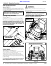
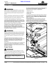
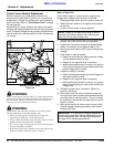
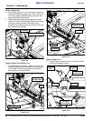
Steering Control Linkage
Figure 3-2
!
WARNING
Make certain mower is secure when it is raised and placed on
the jack stands. The jack stands should not allow the mower to
move when the engine is running and the drive wheels are
rotating. Use only certified jack stands.
!
WARNING
The transaxle fan and pulley assemblies are turning while
making adjustment to the pump linkage rods.
• Always turn off ignition switch before loosing and
tightening the jamb nuts on the linkage rods.
• Always adjust the linkage rods at the flat surface located
farthest from the fan and pulley assembly.
• Do not wear loose clothing that can become entangled in
the fan and pulley assemblies.
• Keep hands and other extremities away from the fan and
pulley assemblies while the engine is running.
Jam Nuts
Jam Nuts
24910
Adjust Pump Linkage Rods
At This Location Only
Fan Mounting
Hardware
(3-Places)
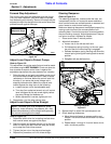
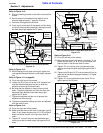
Refer to Figure 3-2:
If the mower creeps in neutral position, adjust pump
linkage rods, located under the seat, as follows:
1. Disengage blade switch and turn ignition switch off.
2. Raise and block mower up to support drive wheels
off the floor.
3. Position control levers in neutral position.
4. Remove fan mounting hardware and transaxle fans if
the jam nuts under the fan are not accessible.
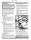
5. Loosen jam nuts at both ends of the pump linkage
rod by 5 or more full turns (approximately 1/4").
6. Start engine and observe which way the wheels are
rotating.
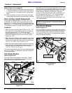
7. If the wheel is rotating forward:
a. Rotate rod to shorten the steering control linkage
until the wheel comes to a stop.
b. Repeat for the opposite side if necessary.
c. When both wheels remain in neutral, turn ignition
switch off and tighten jam nuts at both ends to lock
pump linkage rod(s) in place.
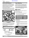
8. If wheel is rotating in reverse:
a. Rotaterod to lengthen steering control linkageuntil
the wheel comes to a stop.
b. Repeat for the opposite side if necessary.
c. When both wheels remain in neutral, turn ignition
switch off and tighten jam nuts at both ends of the
linkage rods.
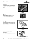
9. Reinstall transaxle fans if removed. Tighten fan
mounting hardware.
10. Start engine and test neutral adjustment again by
moving control levers forward and backward before
returning them to neutral position. The unit is ready
for operation if the tires do not rotate with the control
levers in neutral.
11. With ignition switch off, place control levers in park.
Remove support blocking and safely lower mower
wheels to the floor.
NOTE: Step 4 is not required but may be done if
transaxle fan blades interfere with loosening the
jam nuts on the pump linkage rods.
IMPORTANT: It is important to always readjust the
control lever stops after making adjustments to the
pump linkage rods. See “Forward Stop Adjustment”
on page 21 for adjusting procedures.