


8
Section 1: Assembly & Set-up
Z44 & Z52 (S/N 526171 & Above) Zero Turning Radius Mowers Riding Mowers Accu-Z Razor
®
357-187M
1/12/09
Land Pride
Table of Contents
Section 1: Assembly & Set-up
Uncrating Instructions
The crate is assembled with nails and the mower frame is
secured to the crate floor with metal bands.
1. First, pry off the top panel and then the side panels
and then the end panels.
2. Cut and remove metal bands securing front and rear
wheels to the crate floor. Discard bands.
3. Complete assembly instructions and engine
preparations below before driving mower off the
crate floor.
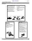
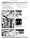
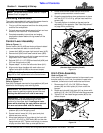
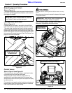
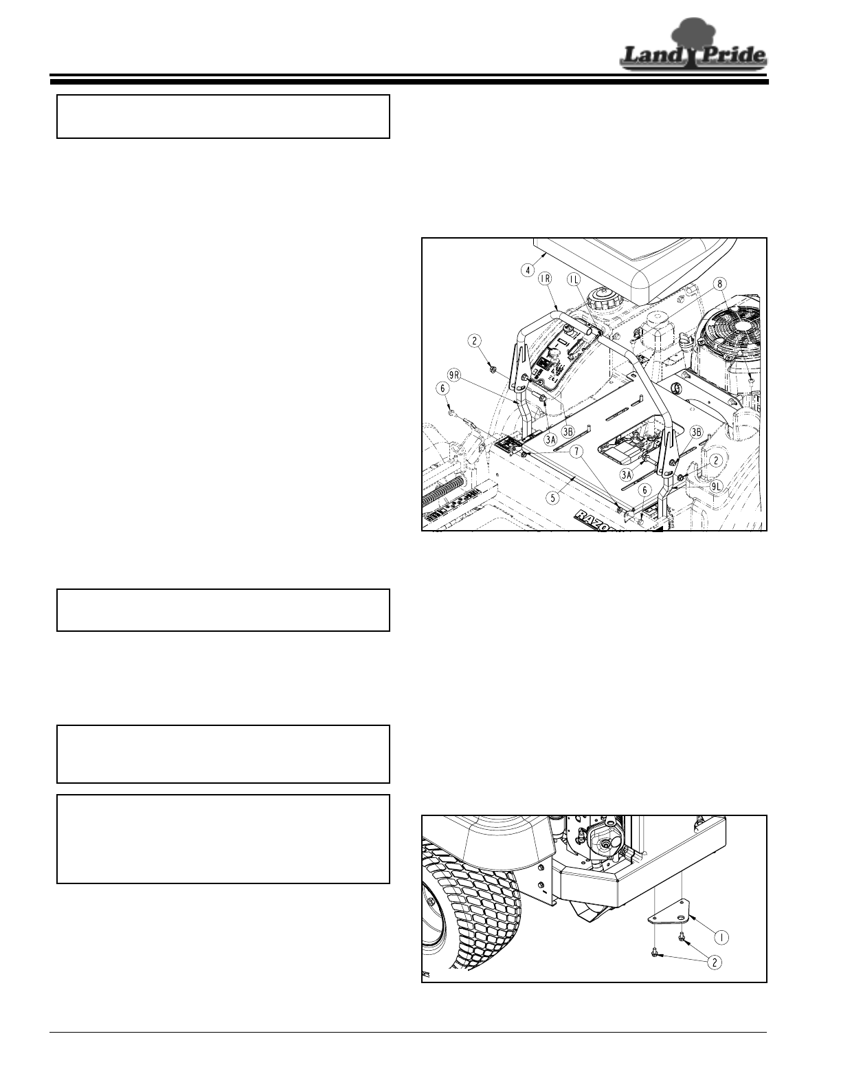
Control Lever Assembly
Refer to Figure 1-1:
Control levers (#1A & #1B) are factory shipped rotated
down and secured with bolts in control levers.
1. Loosen bolt (#3B) on upper right control lever (#1R).
2. Remove bolt (#3A) from lower control lever (#9R).
3. Rotate control lever up until slot in upper control lever
aligns with hole in lower control lever.
4. Reinstall 3/8"-16 1 1/2" GR5 hex head bolt (#3A) and
3/8" hex flange lock nut (#2).
5. Repeat steps 1 to 4 for the left control lever (#1L).
6. Align control lever handles with each other and
tighten bolts (#3A & #3B) to the correct torque.
Seat Assembly
Refer to Figure 1-1:
Seat (#4) is shipped mounted to hinge platform (#5) and
attached to the shipping crate with lag bolts.
1. Remove the two lag bolts securing seat (#4) and
platform (#5) to the shipping crate.
2. Spread control levers (#1) fully apart and pivot
deluxe seat arm rest up.
3. Mount seat platform to hinge tabs at the front with
two 5/16”-18 x 5/8” lg. GR5 bolts (#6) and two hex
flange locknuts (#7). Tighten nuts snugly to remove
all play and then back nuts up one-quarter turn.
NOTE: For correct torque values, refer to “Torque
Values Chart” on page 48.
NOTE: See "Upper Control Lever Adjustments" on
page 22 for final adjustments to the control levers.
IMPORTANT: Be careful not to cut the seat cover
when removing packing material around the seat.
Cutting the seat cover will void its warranty.
IMPORTANT: The arm rests on the Deluxe Seat
must be pivoted up when attaching the seat
platform to the mower deck. Leaving arm rests
down while attaching the seat platform can cut
the arm rest covers and void the warranty.
4. Locate and connect mower switch wires to the
operator pressure switch under the seat.
5. Hinge the seat platform down and secure in place
with two 5/16"-18 x 3/4" lg. phillips head machine
screws (#8).
6. The seat platform is slotted so the seat can be
adjusted to fit the operator. See "Seat Adjustment"
on page 22 for positioning.
Control Lever & Seat Assembly
(Standard Seat Assembly Shown)
Figure 1-1
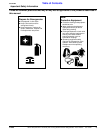
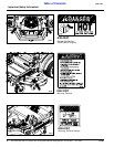
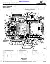
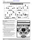
Hitch Plate Assembly
Refer to Figure 1-2:
Hitch plate (#1) is shipped mounted to the mower’s rear
bumper ready for use. If not, the plate will need to be
removed, turned around and remounted as follows:
1. Remove two 5/16"-18 x 5/8" GR5 hex flange
screws (#2) and hitch plate (#1) from under the
bumper.
2. Rotate and reinstall hitch plate (#1) as shown with
existing 5/16"-18 x 5/8" GR5 hex head flange screws.
3. Tighten 5/16" hex head flange screws (#2) to the
correct torque.
Hitch Plate Assembly
Figure 1-2
24896
23624