


25
Section 3: Adjustments
2/27/07
Z44 & Z52 (S/N 472620 -526170) Zero Turning Radius Mowers Riding Mowers Accu-Z Razor
®
357-044M
Land Pride
Table of Contents
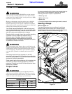
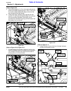
Refer to Figure 3-12 on Page 24:
27. Compress the deck lift assist springs so that there is
1” of space between the front nut and on the spring
and the rear nut on the deck lift block. Typical both
sides.
28. When completed, all chains will be tight, and deck
cutting height will be set to the deck height indicator.
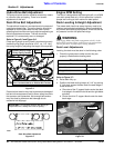
Deck Cutting Height Adjustment
Deck height is adjustable from 1 1/2” to 4 1/2” in 1/4”
increments. The holes in the height adjusting bar are
spaced at 1/2” intervals. By turning the height adjusting
stop around, 1/4” increments can be attained due to the
1/4” plate that is part of the stop. Refer to Figure 3-8.
EXAMPLES:
• When the height adjusting stop is placed in the 1 1/2”
hole, with the 1/4” plate facing to the front of the unit,
the cutting height is at 1 1/2”. When the height
adjusting stop is placed in the 1 1/2” hole, with the 1/4”
plate on the operator’s side of the hole, the cutting
height is at 1 3/4”.
• When the height adjusting stop is placed in one of the
holes, with the 1/4” plate on the operator’s side of the
hole, the deck height will be set at one of the following:
1 3/4”, 2 1/4”, 2 3/4”, 3 1/4”, 3 3/4” or 4 1/4”.
• When the height adjusting stop is placed in one of the
holes, with the 1/4” plate facing to the front of the unit,
the deck height will be set at one of the following:
1 1/2”, 2”, 2 1/2”, 3”, 3 1/2”, or 4”.
The notch located at the rear of the right height adjusting
bar (4 1/2” height) is to used when the deck is placed in
the transport mode.
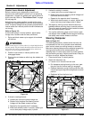
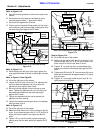
Anti-Scalp Rollers
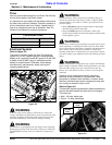
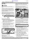
Refer to Figure 3-15:
Anti-scalp rollers are standard on the Razor. These
anti-scalp rollers are designed to minimize scalping
when mowing on rough uneven terrain.
Anti-Scalp Roller Adjustment
Figure 3-15
Adjusting
Holes
Anti-Scalp Rollers
23685
After setting the cutting height, adjust the front anti-scalp
rollers so they extend below the deck but do not contact
the ground. They should always be at least 1/4” to 3/4”
below the deck. With the unit sitting on a flat level
surface, the front wheel position can be adjusted up or
down as needed from 3/4” to 1 3/4” below the blade
surface. Move the front wheels up or down, in 1/2”
increments, using the different axle mount holes in the
roller mount bracket.
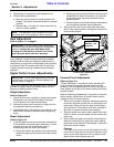
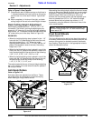
Pivot Front Wheels
Refer to Figure 3-16
The front wheels can be set to pivot about the center of
the mower frame to allow the front wheels to float with the
contour of the ground or locked to prevent the wheels
from floating. Place the pins in the appropriate holes to
obtain the desired functions.
Pivot Locking Pins
Figure 3-16
NOTE: When the anti-scalp rollers are installed, the
minimum cutting height is 1 1/2” with the anti-scalp
rollers set at 3/4”.
Shown In
Locked Position
23685
Float Position