


21
Section 3: Adjustments
2/27/07
Z44 & Z52 (S/N 472620 -526170) Zero Turning Radius Mowers Riding Mowers Accu-Z Razor
®
357-044M
Land Pride
Table of Contents
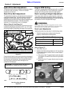
3. Repeat step 2 to adjust the right dampener rod.
4. Check steering dampeners:
a. Move the control levers to reverse position and
release. The control levers should return to neutral
position.
b. Repeat steps 1 through 4 if control levers do not
return to neutral position.
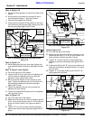
Seat Adjustment
Refer to Figure 1-1 on page 8:
The seat platform is slotted so the seat can be adjusted
to the operator. Loosen the seat mounting hardware
located under the seat and adjust the seat forward or
rearwards to a length that is comfortable for the operator
to raise and lower the mower deck with his right foot.
Tighten the seat mounting hardware once the seat is
adjusted.
Upper Control Lever Adjustments
The control levers may be adjusted while in the neutral
position for height, reach and forward travel to fit the
operator’s steering comfort zone.
Height Adjustment
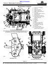
Refer to Figure 3-4:
1. Adjust control levers vertically by removing the bolts,
flat washers, and locknuts that attach the upper
control levers to the lower control levers.
2. Reposition upper control levers to a height that fits
the operator’s personal preference.
3. Reassemble bolts, flat washers, and locknuts in the
same order they were removed without tightening
them.
Reach Adjustment
Refer to Figure 3-4
1. Pivot the upper control levers forward or backward to
fit the operator’s personal reach preference. If reach
comfort zone can not be achieved, then try
exchanging sides the levers are located:
a. Remove the bolts, flat washers, and locknuts that
attach the upper control levers to the lower control
levers.
NOTE: The dampener must not bottom out when
the pump lever is fully stroked in either direction.
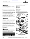
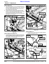
IMPORTANT: The arm rests on the Deluxe Seat
must be pivoted up before hinging the seat platform
forward. Leaving the arm rests down while
hinging the seat platform forward can cut the
arm rest covers and void their warranty.
IMPORTANT: Do not make adjustment to the lower
control levers since they are already adjusted for
neutral creep on page 20.
b. Switch right control lever with left control lever and
reassemble the bolts, flat washers, and locknuts
in the same order they were removed without
tightening them.
c. Pivot the upper control levers forward or backward
to fit operator’s personal reach preference.
2. Verify that the control levers align with each other
when in the neutral position and tighten the locknuts
to the correct torque.
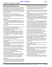
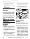
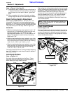
Control Lever Adjustment
Figure 3-4
Forward Travel Adjustment
Refer to Figure 3-4:
"Reach Adjustment" instructions are for adjusting the
control levers to be equally aligned while in neutral.
However, with this adjustment, the mower may want to
steer slightly to the right or left when pushing the levers
equally forward.
Make the following adjustments if you prefer to have the
levers equally aligned while in forward travel position
instead of while in neutral position:
1. While driving forward, make the necessary steering
correction required to make the unit go straight and
take careful notice of how the upper control levers
are positioned. (The distance one lever is ahead of
the other to make the mower travel straight.)
2. Stop the mower on a level surface, place the control
levers in neutral, shut the power off and remove the
switch key.
3. Either adjust the upper trailing lever forward by the
distance it was trailing or adjust the upper leading
lever back by the distance it was leading. Tighten the
locknuts to correct torque.
Example:
If the right control lever is one inch ahead of the left
control lever, stop the unit and either adjust the right
upper control lever back one inch or adjust the left
upper control lever forward one inch.
Bolts with Flat
Washers, and
Locknuts
Lower Control Lever
Upper Control Lever
23626