


8
Section 1: Assembly & Set-up
Z44 & Z52 (S/N 472620 -526170) Zero Turning Radius Mowers Riding Mowers Accu-Z Razor
®
357-044M
2/27/07
Land Pride
Table of Contents
Section 1: Assembly & Set-up
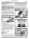
Uncrating Instructions
The crate is assembled with wire clips. The mower frame
is banded to the crate floor.
1. First remove the top panel by prying the wire clips
free with a pry bar. Then remove the side panels in
the same way.
2. Cut metal bands securing front wheels to the crate
floor. Discard bands.
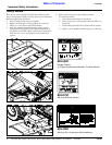
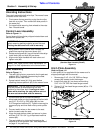
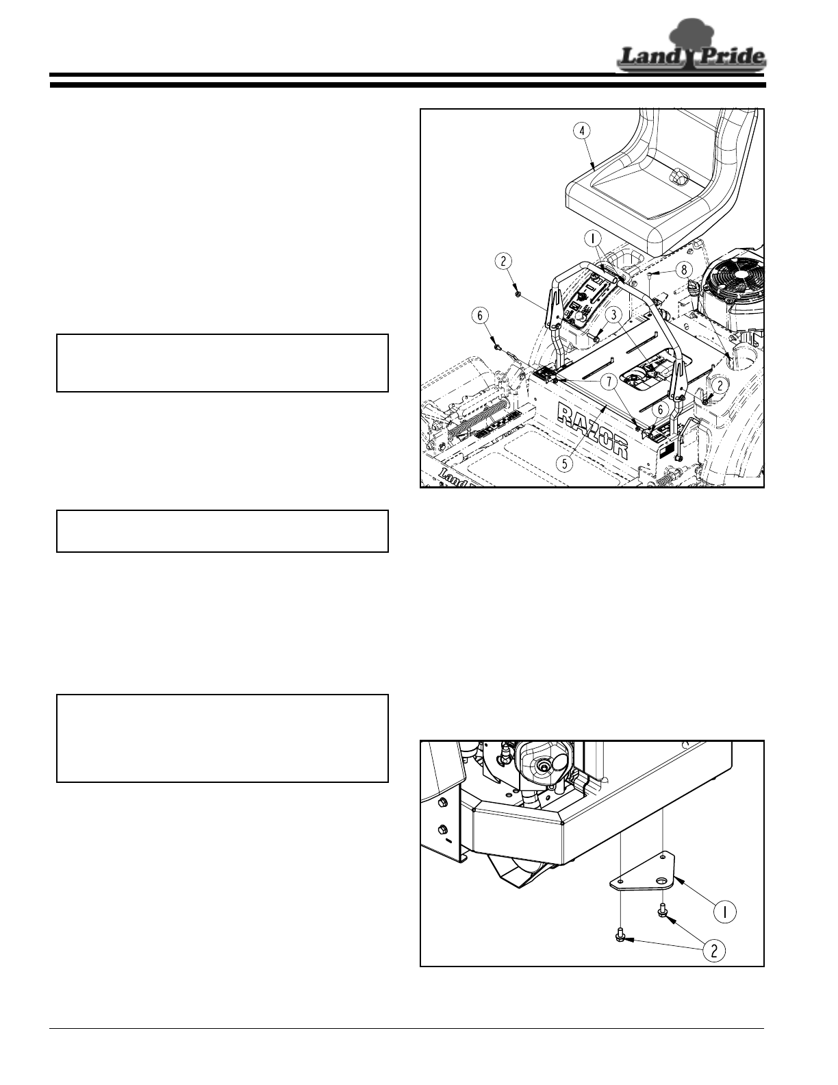
Control Lever Assembly
Refer to Figure 1-1:
Control levers (#1) are factory shipped rotated down and
secured with plastic ties.
1. Being careful not cut control lever handles, cut
plastic ties securing the control levers (#1).
2. Rotate control levers (#1) up until the bolt holes align.
Install bolts (#3) and nuts (#2) as shown.
3. Align control lever handles with each other and
tighten nuts (#2).
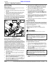
Seat Assembly
Refer to Figure 1-1:
1. The seat (#4) is factory mounted to the hinged seat
platform (#5). Cut plastic ties securing the seat
platform to the crate frame.
2. Spread control levers (#1) fully apart before
attaching the seat platform (#5) to the mower frame.
3. Pivot the arm rest on the Deluxe Seat up.
4. Mount seat platform to the hinge tabs at the front with
two 5/16”-18 x 5/8” lg. GR5 bolts (#6) and two
5/16” flange hex locknuts (#7). Tighten nuts snugly to
remove all play and then back nuts up one-quarter
turn.
5. Connect switch wires on the mower to the seat
switch located under the seat.
6. Hinge the seat platform down and secure in place
with two 5/16"-18 x 3/4" lg. phillips head machine
screws (#8).
7. The seat platform is slotted so the seat can be
adjusted to fit the operator. See "Seat Adjustment"
on page 21 for positioning.
IMPORTANT: Be careful not to cut the seat cover
when removing packing material around the seat.
Cutting the seat cover will void its warranty.
NOTE: See "Upper Control Lever Adjustments" on
page 21 for final adjustments to the control levers.
IMPORTANT: The arm rests on the Deluxe Seat
must be pivoted up when attaching the seat
platform to the mower deck. Leaving arm rests
down while attaching the seat platform can cut
the arm rest covers and void the warranty.
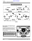
Control Lever & Seat Assembly
(Standard Seat Assembly Shown)
Figure 1-1
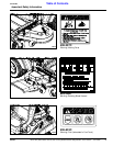
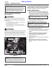
Hitch Plate Assembly
Refer to Figure 1-2:
A hitch plate (#1) is supplied with the mower and is
shipped packaged with the manual.
1. Remove two 5/16"-18 x 5/8" GR5 hex flange
screws (#2) located under the bumper.
2. Install hitch plate (#1) as shown with existing
5/16"-18 x 5/8" GR5 hex head flange screws.
3. Tighten 5/16" hex head flange screws (#2) to 17 ft.
lbs. of torque.
Hitch Plate Assembly
Figure 1-2
23623
23624