


20
Section 3: Adjustments
Z44 & Z52 (S/N 472620 -526170) Zero Turning Radius Mowers Riding Mowers Accu-Z Razor
®
357-044M
2/27/07
Land Pride
Table of Contents
Control Lever Neutral Adjustment
Before considering any adjustment, check tire air
pressure and make certain hydraulic oil is at operating
temperature. Unequal tire pressure will cause mower to
drift to one side. Refer to “Tire Inflation Chart” on page
22 and page 44.
Adjustments for neutral position is made to the pump
linkage rods located between the control lever and pump
arms. The pump linkage rods are properly adjusted when
control levers are in neutral position and drive wheels are
not turning.
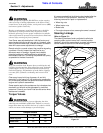
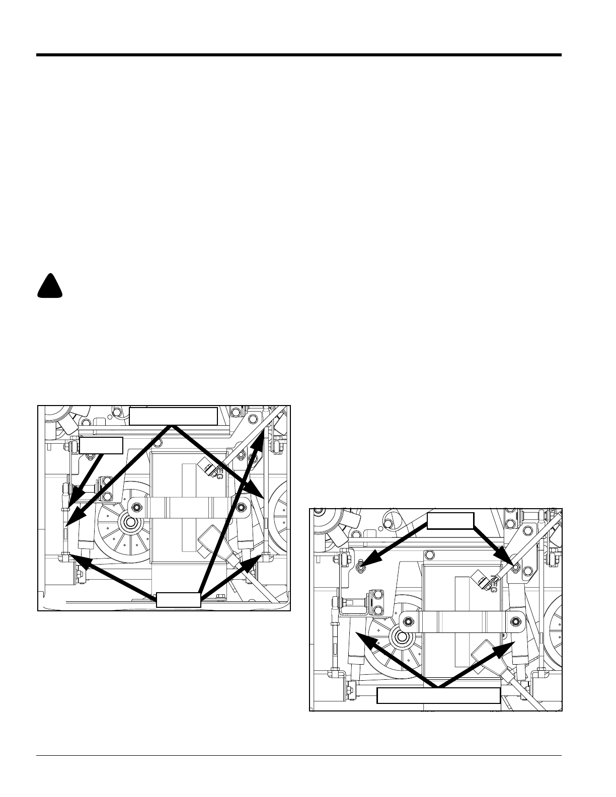
Refer to Figure 3-2:
If the mower creeps in neutral position, adjust pump
linkage rods, located under the seat, as follows:
1. Raise and block mower up to support drive wheels
off the floor.
!
WARNING
Make certain mower is secure when it is raised and placed on
the jack stands. The jack stands should not allow the mower to
move when the engine is running and the drive wheels are
rotating. Use only certified jack stands.
2. Position control levers in neutral position and
disengage blades.
3. Start engine and observe which way the wheels are
rotating.
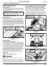
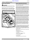
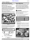
Steering Control Linkage
Figure 3-2
4. If wheel is rotating forward:
a. Loosen jam nuts on the pump linkage rod.
b. Rotate rod to lengthen the steering control
linkage until the wheel comes to a stop.
c. Repeat for the opposite side if necessary.
d. When both wheels remain in neutral, tighten jam
nuts to lock pump linkage rod(s) in place.
20684
Pump Linkage Rod
Jam Nut
Jam Nut
5. If wheel is rotating in reverse:
a. Loosen jam nuts on pump linkage rod.
b. Rotaterod to shorten steering control linkage until
the wheel comes to a stop.
c. Repeat for the opposite side if necessary.
d. When both wheels remain in neutral, tighten jam
nuts to lock the pump linkage rod(s) in place.
6. Test again by moving control levers forward and
backward before returning them to neutral position.
The unit is ready for operation if the tires do not rotate
with the control levers in neutral.
7. Turn ignition switch off, place control levers in park
and set park lever to (ON). Remove support blocking
and safely lower mower wheels to the floor.
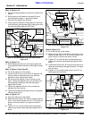
Steering Dampener
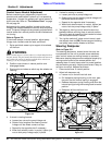
Refer to Figure 3-3:
The steering dampeners, located under the seat, are
incorporated into the unit to provide some resistance
when control levers are moving forward or rearward.
Make sure steering dampeners are adjusted properly by
moving control levers to the reverse position and
releasing them. If control levers return to neutral position,
they are working correctly. Adjust control levers if they do
not return to neutral. Adjusted as follows:
1. Place control lever in neutral position.
2. Adjust left dampener rod:
a. Loosen nut on the left front ball stud.
b. Pull dampener spring housing, to the rear, past
the point that the internal spring is engaged.
c. Release dampener spring housing and allow the
internal spring to bring the housing back to neutral
position.
d. Retighten left front ball stud nut.
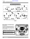
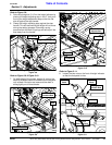
Steering Dampener
Figure 3-3
20684
Ball Stud
Dampener Spring Housing