


PAGE 4 — DCA70SSJU4i
TABLE OF CONTENTS
DCA70SSJU4i 60 Hz
Generator
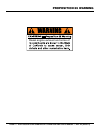
Proposition 65 Warning ........................................... 2
Reporting Safety Defects ......................................... 3
Table Of Contents .................................................... 4
Safety Information .............................................. 6-11
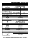
Generator/Engine Specifications ........................... 12
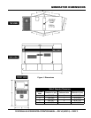
Generator Dimensions ........................................... 13
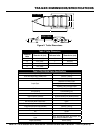
Trailer Dimensions/Specifications .......................... 13
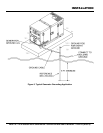
Installation ........................................................ 16-17
General Information ............................................... 18
Generator Major Components ............................... 19
Trailer Major Components ..................................... 20
Engine Control Unit (ECU) .................................... 21
Engine/Generator Control Panel............................ 22
Output Terminal Panel Familiarization .............. 23-25
Load Application .................................................... 26
Generator Outputs ................................................. 27
Generator Outputs/Gauge Reading ....................... 28
Output Terminal Panel Connections ................. 29-30
600 VAC Connections (Option) .............................. 31
Inspection/Setup ............................................... 32-35
Generator Start-Up Procedure (Manual Mode) 36-37
Generator Start-Up Procedure (Auto Mode) .......... 38
Generator Shut-Down Procedures ........................ 39
Generator/Engine Maintenance ........................ 40-46
Trailer Maintenance .......................................... 47-49
Trailer Guidelines .............................................. 50-64
Troubleshooting Diagnostics ................................. 66
Troubleshooting Generator ................................... 67
Troubleshooting Engine .................................... 68-69
Generator Wiring Diagram ..................................... 70
600 VAC Auto Transformer Wiring Diagram (Option) .. 71
Engine Wiring Diagram .......................................... 72
Battery Charger Wiring Diagram (Option) ............. 73
Water Heating Element Wiring Diagram (Option) .. 74
Explanation Of Code In Remarks Column............. 75
Suggested Spare Parts ......................................... 77
Component Drawings
Generator Assembly ......................................... 78-79
Control Box Assembly ...................................... 81-83
Engine And Radiator Assembly ........................ 84-87
Output Terminal Assembly ................................ 88-89
Battery Assembly ............................................. 90-91
Muffler Assembly ............................................. 92-93
Fuel Tank Assembly .......................................... 94-95
Enclosure Assembly ......................................... 96-99
Rubber Seals Assembly ............................... 100-101
Camlock Assembly ....................................... 102-103
Battery Charger Assembly............................ 104-105
Heating Element Assembly .......................... 106-107
3-Phase 600 VAC Transformer Assembly ..... 108-109
Trailer Assembly (TRLR70USH) ................... 110-111
Trailer Assembly (TRLR70USE) ................... 112-113
Nameplate And Decals Assembly ................ 114-117
Terms And Conditions Of Sale — Parts .............. 118
NOTICE
Specifications are subject to change without notice.