


PAGE 24 — DCA70SSJU4i
OUTPUT TERMINAL PANEL FAMILIARIZATION
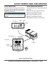
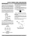
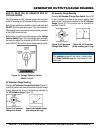
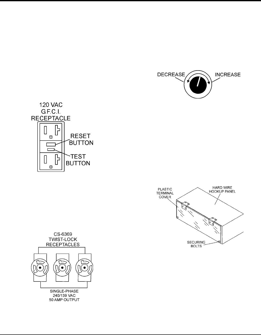
There are two 120 VAC, 20 amp GFCI (Duplex Nema 5-20R)
receptacles provided on the output terminal panel. These
receptacles can be accessed in any voltage change-over
board configuration. Each receptacle is protected by a 20
amp circuit breaker. These breakers are located directly
above the GFCI receptacles. Remember the load output
(current) of both GFCI receptacles is dependent on the
load requirements of the U, V, and W output terminal lugs.
Pressing the reset button resets the GFCI receptacle after
being tripped. Pressing the test button (See Figure 9) in
the center of the receptacle will check the GFCI function.
Both receptacles should be tested at least once a month.
Figure 9. G.F.C.I. Receptacle
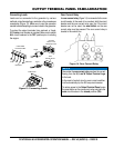
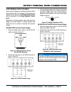
There are three 240/139V, 50 amp auxiliary twist-lock (CS-
6369) receptacles (Figure 10) provided on the output
terminal panel. These receptacles can only be accessed
when the voltage change-over board is configured for
application
Figure 10. 240/139V Twist-Lock Auxiliary
Receptacles
Each auxiliary receptacle is protected by a 50 amp circuit
breaker. These breakers are located directly above the
GFCI receptacles. Remember the load output (current) on
all three receptacles is dependent on the load requirements
of the output terminal lugs.
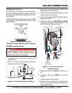
Turn the voltage regulator control knob (Figure 11) on
the control panel to obtain the desired voltage. Turning the
knob clockwise will increase the voltage, turning the knob
counter-clockwise will decrease the voltage.
Figure 11. Voltage Regulator Control Knob
The Output Terminal Lugs are protected by a plastic
face plate cover (Figure 12). Un-screw the securing bolts
and lift the plastic terminal cover to gain access to the
terminal enclosure.
After the load wires have been securely attached to the
terminal lugs, reinstall the plastic face plate.
Figure 12. Plastic Face Plate
(Output Terminal Lugs)