


DCA70SSJU4i
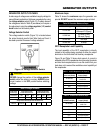
3Ø, 600 VAC can be achieved via the auto-transformer
module. This module provides the necessary electronics
to convert the 3Ø, 480 VAC inut voltage to a 3Ø, 600 VAC
output voltage.
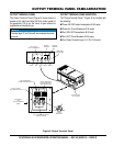
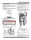
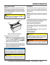
The 3Ø, 600 VAC ouput voltage cannot be achieved unless
the voltage selector switch (Figure 29) is placed in the 3Ø,
480/277 position.
Figure 29. Voltage Selector Switch
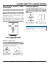
3Ø-240/139V Position (600 VAC Auto-Transformer)
1. Loosen the latches on the control box enclosure and
open the door.
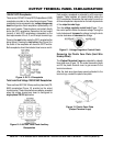
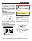
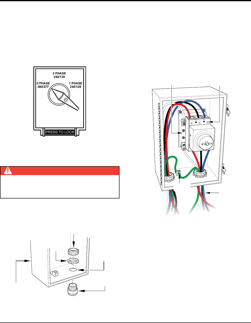
2. Drill a 1-1/2 inch hole at the bootom control box
enclosure as shown in Figure 30.
Figure 30. Control Box Enclosure (Drilling)
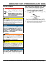
DANGER
When connecting the load wires make sure the
generator is The possibility of electrocution exists
causing severe bodily harm even death!
CIRCUIT BREAKER
ENCLOSURE
DRILL
NEW HOLE
(1-1/2” DIA.)
STRAIGHT
FITTING
LOCK
RING
BUSHING
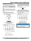
3. After drilling, make sure all shavings and debris have
been removed from the enclosure.
4. Install customer supplied conduit, fittings and bushing
through enclosure hole opening.
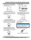
5. Next, route the customer supplied 5 wires through the
straight conduit fitting.
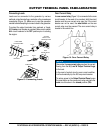
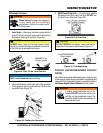
6. Connect the 3 load wires (RED, and )
to the load side (bottom) of the circuit breaker,, T2
and respectively. Reference Figure 31
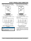
Figure 31. Control Box Enclosure
Load Connections
7. Connect the neutral wire ( to the neutral bus
bar.
8. Connect the ground wire (GREEN) to the ground
terminal.
9. Torque all wires to 45 lbf-in (5 N
.
m).
10. Once all wires have been securely tighten, close
control box enclosure door and securely tighten the
control box door latches.
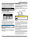
L1
T1
T2
T3
L2
L3
70 AMP
CIRCUIT BREAKER
LOAD
WIRES
FROM
600 VAC
AUTO
TRANSFORMER
NEUTRAL BUS BAR
GROUND
TERMINAL
600 VAC CONNECTIONS