


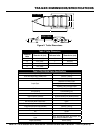
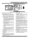
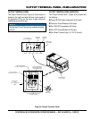
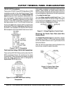
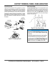
PAGE 22 — DCA70SSJU4i
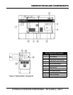
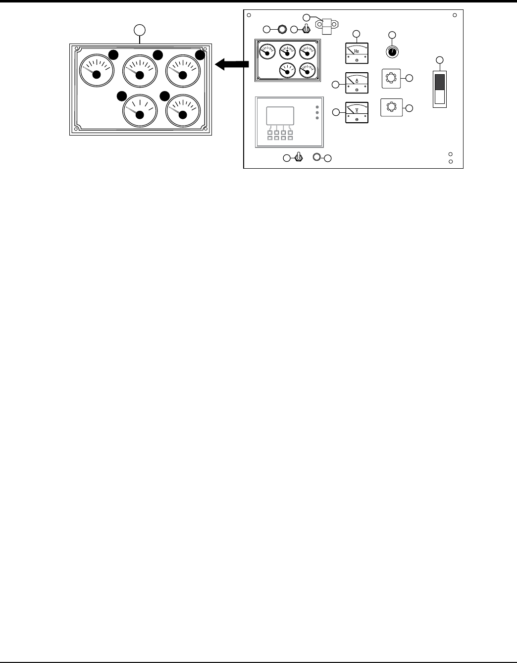
ENGINE/GENERATOR CONTROL PANEL
The definitions below describe the controls and functions
of the Engine/Generator Control Panel (Figure 7).
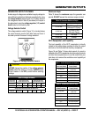
1. Gauge Unit Assembly — This assembly houses the
various engine monitoring gauges. These gauges
indicate: oil pressure, water temperature, charging
voltmeter, fuel and engine speed RPM (tachometer).
A. Oil Pressure Gauge — During normal operation
this gauge be should read between 35 to 65 psi.
(241~448 kPa). When starting the generator the
oil pressure may read a little higher, but after the
engine warms up the oil pressure should return to
the correct pressure range.
B. Water Temperature Gauge — During normal
operation this gauge be should read between 185°
and 207°F (85°~97°C).
C. — During normal
operation this gauge indicate minimum 14 VDC
D. Fuel Gauge — Indicates amount of diesel fuel
available.
E. Tachometer — Indicates engine speed in RPM’s
for 60 Hz operation. This meter should indicate
1800 RPM’s when the rated load is applied.
2. — This lamp when
ON indicates that fluids in the containment area have
reach a high level.
3. — When activated will turn on
control panel light.
4. — For operation at night, panel light
illuminates control panel for ease of reading meters
and gauges. Make sure panel light switch is in the OFF
position when light is not in use.
PSI
OIL PRESS
0
25
50
75
100
°F
WATER TEMP
100
140
180
220
260
VOLTS
BATTERY
6
12
18
24
30
°F
FUEL
E
½
F
RPMX10
SPEED
0
120
150
180
210
60
D
A
B C
E
1
OFF
W
U
V
OFF
W-U
V-W
U-V
DECREASE
INCREASE
PSI
OIL PRESS
0
25
50
75
100
°F
WATERTEMP
100
140
180
220
260
VOLTS
BATTERY
6
12
18
24
30
FUEL
E
½
F
RPMX10
SPEED
0
120
150
180
210
60
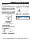
Series 800 Controller
ECU
Engine Started
Shutdown
Pre-Alarm
Alarm
Acknowledge
Screen
Change
Program
Exit
Option
2
3
4
5
6
7
8
9
10
11
12
13
Figure 7. Engine/Generator Control Panel
5. — Indicates the output frequency
in hertz (Hz). Normally 60 Hz
6. AC Ammeter — Indicates the amount of current the
load is drawing from the generator per leg selected by
the ammeter phase-selector switch.
7. — Indicates the output voltage present
at the
8. — Allows ±15% manual
adjustment of the generator’s output voltage.
9. — This switch allows
the AC ammeter to indicate the current flowing to the load
connected to any phase of the output terminals, or to be
switched off. This switch does not effect the generator
output in any fashion, it is for current reading only.
10. — This switch allows
the AC voltmeter to indicate phase to phase voltage
between any two phases of the output terminals or to
be switched off.
11. — This three-pole, 200 amp
main breaker is provided to protect the
from overload.
12. — This switch selects either manual
or automatic operation . Center position is OFF (reset).
13. — With the engine stopped, press
and hold this button. The total running hours, fuel level,
and battery voltage will be displayed.