


DCA70SSJU4i
GENERATOR START-UP PROCEDURE (MANUAL MODE)
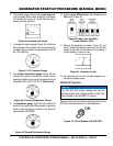
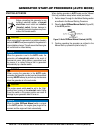
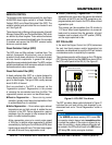
6. The ammeter (Figure 46) will indicate zero amps with
no load applied. When a load is applied, the ammeter
will indicate the amount of current that the load is
drawing from the generator.
Figure 46. Ammeter (No Load)
7. The engine oil pressure gauge (Figure 47) will indicate
the oil pressure of the engine. Under normal operating
conditions the oil pressure is approximately 35 to 65
psi. (193~586 kPa).
Figure 47. Oil Pressure Gauge
8. The coolant temperature gauge (Figure 48) will
indicate the coolant temperature. Under normal
operating conditions the coolant temperature should
be between 180°~225°F (75°~95°C) (Green Zone).
Figure 48. Coolant Temperature Gauge
9. The tachometer gauge (Figure 49) will indicate the
speed of the engine when the generator is operating.
Under normal operating conditions this speed is
approximately 1800 RPM’s.
Figure 49. Engine Tachometer Gauge
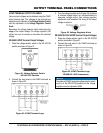
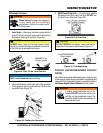
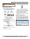
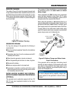
10. Place the circuit breakers in the
ON position (Figure 50).
Figure 50. Main, Aux. and GFCI
Circuit Breakers (ON)
11. Observe the generator’s ammeter (Figure 51) and
verify it reads the anticipated amount of current with
respect to the load. The ammeter will only display a
current reading if a load is in use.
Figure 51. Ammeter (Load)
12. The generator will run until manually stopped or an
abnormal condition occurs.
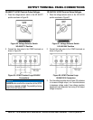
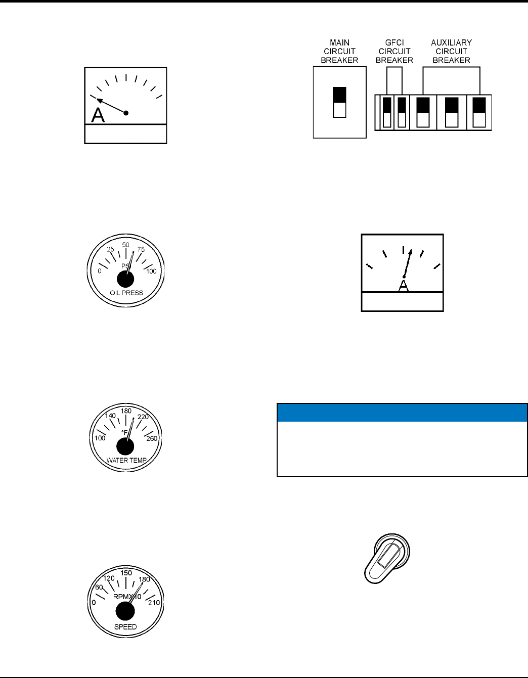
Place the 70 amp circuit breaker switch (Figure 52) on the
600 VAC control box enclosure to the ON position.
Figure 52. Circuit Breaker ON (600 VAC)
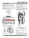
NOTICE
The 3Ø, 600 VAC output voltage can only be
achieved when the voltage selector switch has
been placed in the
3Ø-480/277V position.
ON