


28 Assembly
WPMAN0142 (Rev. 9/1/2004)
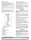
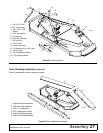
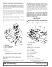
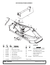
Optional Front Roller Installation (Figure 26)
The optional front roller is designed to carry the center
of the mower over uneven ground, minimizing scalping.
Front roller mounting brackets use the four mounting
bolts of the gear stand.
Remove the gear stand front mounting bolts. Hole pat-
terns in the mounting brackets (1 & 2) determine right
and left. Position these brackets with the highest hole
to the rear, the middle hole forward, and the bracket
angle outward as shown.
Attach brackets with the carriage bolts (3) and flange
locknuts (7) provided with the front roller kit.
Place roller (5) between the brackets and insert rod (6)
through brackets and roller, securing with cotter pins
(4).
Figure 26. Optional Front Roller Installation
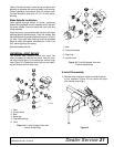
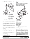
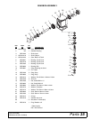
Quick Hitch Kit Installation (Optional)
(Figure 27)
Note: This kit allows mower to fit only Cat. 1 standard
ASAE quick hitch.
Attach offset link (1) to mounting pins, using 7/8" sleeve
(8) and flat washer (9). Attach upper end of offset link
to pivot link, using 1/2" flat washer (5), sleeves (6 &
10), flange lock nut (7), and 1/2 x 4-3/4" cap screw.
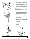
Remove rear offset links and replace with chains (2),
cut to required length. Attach chain to top of A-frame as
shown, using 1/2 x 6" cap screw (4), 1/2" flat washer
(5), and nut.
Attach opposite end of chain (2) to rear mower frame
as shown. Cut chain to 45" (1143 mm) in length. Vary
length slightly as desired. Twist chain to make finite
adjustments in length until unit lifts level. Do not bottom
out the drive on front of deck.
IMPORTANT
Failure to follow instructions may result in dam-
age.
Install sleeve (3) on mounting pins and retain with Klik
pin.
1. Offset link
2. 38-Link chain
3. 29/32 x 1-7/16 x 1-1/4" Sleeve
4. 1/2" x 6 Cap screw
5. 1/2" Flat washer
6. 1/2" x 3/4" x 3-3/8" Sleeve
7. 1/2" Flange lock nut
8. 7/8" Sleeve
9. 7/8" Flat washer
10. 13/16 x 1-1/4 x 1-13/16" Sleeve
Figure 27. Quick Hitch Kit Assembly
(GM1072S shown)
7
3
2
4
1
CD4001
5
6
1. Right bracket
2. Left bracket
3. 3/8 x 1" Carriage bolt
4. 3/16 x 1" Cotter pin
5. Front roller
6. Rod
7. 3/8" Flanged locknut
CD608
0
A
5
5
7
6
10
5
5
2
5
4
3
5
1
9
8
1/2 x 4-3/4 HHCS