


Dealer Service 21
WPMAN0142 (Rev. 9/1/2004)
Lightly lubricate top seal, locate spring and place seal
squarely on housing with spring up away from housing.
Follow installation instructions given for bottom seal.
Top seal should be flush with, to 1/16" (2 mm) above,
housing.
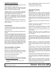
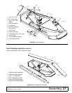
Blade Spindle Installation
Insert spindle through bottom of mower, positioning
grease fitting outward on outer spindles and to the rear
on center spindle. Secure to deck with four bolts and
flange locknuts.
Place belt pulley over spindle shaft and seat split taper
bushing against spindle sleeve. Place flat washer and
bolt into threads of spindle shaft and torque to 35 lbs-ft
(47 Nm). Place split taper bushing bolts into threaded
holes of pulley and tighten alternately to 12 lbs-ft (16
Nm), securing pulley to bushing.
Reinstall blades and belt.
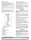
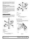
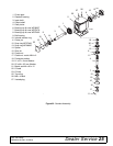
UNIVERSAL JOINT REPAIR
Two different style driveline U-joints are used. The
repair procedure is basically the same. One has inter-
nal snap rings (Figure 14); the other has external snap
rings (Figure 15). Determine which type you are repair-
ing and remove all four snap rings.
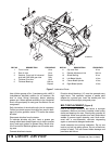
1. Yoke
2. Journal cross
3. Seal
4. Snap ring
5. Cup and bearings
6. Yoke
Figure 14. U-Joint Exploded View with
Internal Snap Rings
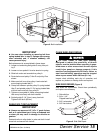
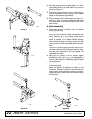
1. Yoke
2. Cup and bearings
3. Snap ring
4. Journal cross
Figure 15. U-Joint Exploded View with
External Snap Rings
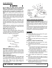
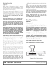
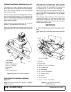
U-Joint Disassembly
1. Remove snap rings from inside or outside of yokes
in four locations. (Figure 16 only shows the style
with internal snap rings.)
Figure 16
CD1402
6
1
2
3
4
5
CD1645A
3
3
3
3
2
2
2
2
4
1
1
CD1384