


24 Dealer Service
WPMAN0142 (Rev. 9/1/2004)
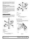
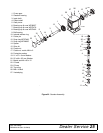
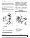
Gearbox Assembly
(Figure 22)
NOTE: Repair of this gearbox is limited to replacing
bearings, seals, and gaskets. Replacing gears, shafts,
and a housing is not cost effective. Purchasing a com-
plete gearbox is more economical.
Clean housing, paying specific attention to the areas
where gaskets will be installed. Wash housing and all
components thoroughly. Select a clean area for gear-
box assembly. Replace all seals, bearings, and gas-
kets. All parts must be clean and lightly oiled before
reassembling.
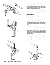
Insert output bearings (6 & 7) in the housing, using a
round tube of the correct diameter and a hand press.
Slide output shaft (4) through both bearings (6 & 7)
until it rests against bearing (6). Slide shim (15) over
output shaft (4). Press gear (5) onto output shaft (4)
and secure with washer (20), castle nut (16), and cotter
pin (11).
Apply grease to lower seal lips (21) and press seal (21)
over output shaft (4), using a tube of the correct diame-
ter. Be sure not to damage the seal lip. Press in hous-
ing so that seal is recessed. Insert protective washer
(19) by hand. Install snap ring (10) and position it
together with dual lip seal (21) by pressing into posi-
tion. Verify that snap ring is seated correctly.
Press bearing (8) into the housing, using a round tube
of the correct diameter and a hand press. Secure with
shim (15) and snap ring (12). Secure snap ring (13) on
input shaft (3) if not already secure.
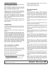
Place gear (1) through top of housing and align gear
(1) and gear (5) so that gear teeth are a match. While
holding gear (1) in place, slide input shaft (3) through
gear (1) and bearing (8). Align splines on shaft (3) and
gear (1).
Slide spacer (14) over input shaft (3) and press bearing
onto input shaft (3), using a round tube of the correct
diameter and a hand press. Slide shim (15) over input
shaft (3) and secure with snap ring (12).
Check input shaft end float by moving the input shaft
(3) by hand. If end float is higher than 0.012" (0.305
mm), insert shim between input shaft (3) and rear bear-
ing (8). Repeat until end float is less than 0.012".(0.305
mm) Check rotational torque by hand. The torque
should be less than 2.2 lbs-inch (0.25 Nm). Check that
the gear backlash is between 0.006" and 0.016" (0.152
- 0.406 mm). You should not have to adjust the back-
lash.
Press in input oil seal (22), using a tube of the correct
diameter. Be careful not to damage the seal lip. Press
oil cap (23) on to cover the rear of housing, using a
tube of the correct diameter.
Check gearbox housing for leaks by plugging all holes
except one. Apply 4 psi compressed air and immerse
the gearbox in water to verify that there are no leaks.
Remove gearbox from water and dry off with com-
pressed air. Add SAE 80W or 90W EP oil until it runs
out of side level hole. Tighten all plugs.
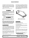
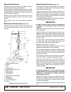
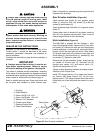
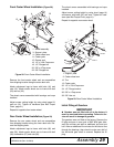
Drive Pulley Installation
(Figure 21)
Invert gear stand.
Install drive pulley and split taper bushing with key on
gearbox vertical shaft.
The distance between the centerline of the lower pulley
and the bottom of the gear stand is critical. Place a
straightedge along the bottom of the gear stand and
measure from it to the centerline of the pulley. This
measurement should be 2.35" (60 mm), plus or minus
.03" (0.76 mm). Variation from this dimension could
cause belt misalignment and premature belt failure.
Tighten the bolts in the split taper bushing alternately
until they are torqued to 12 lbs-ft (16 Nm). Check the
dimension when tightening is complete; remove and
realign if the dimension was not held.
Install the gear stand on the mower frame.
Install the belts, driveline and driveline shielding.
Figure 21. Drive Pulley Installation
2.35 .03”
CD3948
2.35” ± .03”
(60 mm ± 0.76)