


22 Dealer Service
WPMAN0142 (Rev. 9/1/2004)
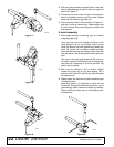
Figure 17
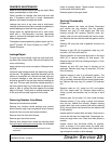
Figure 18
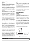
Figure 19
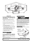
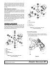
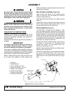
2. With snap rings removed, support drive in vise, hold
yoke in hand and tap on yoke to drive cup up out of
yoke. See Figure 17.
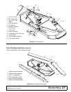
3. Clamp cup in vise as shown in Figure 18 and tap on
yoke to completely remove cup from yoke. Repeat
steps two and three for opposite cup.
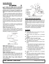
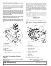
4. Place universal cross in vise as shown in Figure 19
and tap on yoke to remove cup. Repeat step three
for final removal. Drive remaining cup out with a drift
and hammer.
U-Joint Assembly
1. Place seals securely on bearing cups (on internal
snap ring style only).
Insert cup into yoke from outside and press in with
hand pressure as far as possible. Insert journal
cross into bearing cup with grease fitting away from
shaft. Be careful not to disturb needle bearings.
Insert another bearing cup directly across from first
cup and press in as far as possible with hand pres-
sure.
Trap cups in vise and apply pressure. Be sure jour-
nal cross is started into bearings and continue pres-
sure with vise, squeezing in as far as possible. Tap
yoke to aid in process.
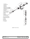
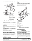
2. Seat cups by placing a drift or socket (slightly
smaller than the cup) on cup and rapping with a
hammer. See Figure 20. Install snap ring and repeat
on opposite cup.
3. Repeat steps one and two to install remaining cups
in remaining yoke.
Move both yokes in all directions to check for free
movement. Should movement be restricted, rap on
yokes sharply with a hammer to relieve any tension.
Repeat until both yokes move in all directions with-
out restriction.
Figure 20
CD1386
CD1387
CD1388
CD1389