


10 Operation
WPMAN0142 (Rev. 9/1/2004)
When driveline is attached to tractor, attach front drive-
line shield tether chain to the tractor to prevent drive-
line shield rotation.
After mower is attached to tractor, carefully raise
mower and check for driveline clearance between drive
shielding and front of mower frame; a minimum of 1/2"
(13 mm) clearance is required. Adjustment to tractor
upper lift stop may be required to prevent driveline from
coming in contact with mower frame.
Make sure spring-activated locking pin or collar
slides freely and is seated firmly in tractor PTO
spline groove.
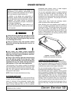
Cutting Height Adjustment for Mounted
Mowers (Figure 2)
IMPORTANT
Avoid very low cutting heights. Striking the
ground with blades produces one of the most dam-
aging shock loads a mower can encounter. Allow-
ing blades to contact ground repeatedly, will cause
damage to mower and drive.
Keep all persons away from operator control
area while performing adjustments, service, or
maintenance.
Best mowing results will be obtained with front of
mower slightly lower than the rear.
Before working underneath, raise mower to
highest position and block securely. Blocking up
prevents mower dropping due to hydraulic leak
down, hydraulic system failures, or mechanical
component failures.
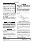
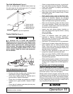
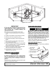
Figure 2. Cutting Height Adjustment
The cutting height will be the distance between the
blade and the ground. The blades are approximately 5
(127 mm) below the top of the mower frame. To check
cutting height, place a straight edge along top edge of
mower frame as shown in Figure 2.
Measure from bottom of straightedge to the ground at
locations “A” and “B”. Subtract 5" (127 mm) from mea-
surement “B” to determine cutting height.
Remember, measurement at location “A” should be at
least 1/4" (6 mm) greater than location “B”, and not
more than 1/2" (13 mm) greater than location “B”.
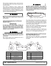
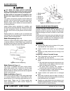
Cutting Height Adjustment with Front and
Rear Caster Wheels (Figure 3)
Place the front and rear adjustment in corresponding
lettered holes. Refer to the chart for approximate cut-
ting height.
Figure 3. Cutting Height Adjustment with Front Caster Wheels
WARNING
WARNING
WARNING
AB
CD3954A
CD3995C
D
C
B
A
E-- H
I--L
D
C
B
A
E-- H
I--L
HOLE NO APPROX. CUTTING HEIGHT
G 4.00" (102 mm)
H 4.50" (114 mm)
I 5.00" (127 mm)
J 6.00" (152 mm)
K 7.00" (178 mm)
L 8.00" (203 mm)
HOLE NO APPROX. CUTTING HEIGHT
A 1.00" (25 mm)
B 1.50" (38 mm)
C 2.00" (51 mm)
D 2.50" (64 mm)
E 3.00" (76 mm)
F 3.50" (89 mm)