


20 Dealer Service
WPMAN0142 (Rev. 9/1/2004)
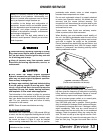
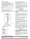
Blade Spindle Removal
Remove belt. Remove blades from spindle. Remove
bolt and washer from top of spindle shaft.
Remove split taper bushing (located on top of pulley)
by removing the two bolts and inserting them into the
threaded holes in bushing flange. Tighten alternately to
remove split taper bushing.
Remove key and pulley. Remove the four bolts and
nuts attaching spindle to mower frame and remove
spindle.
Store bushing, pulley and all hardware for reinstalla-
tion.
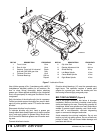
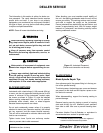
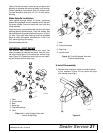
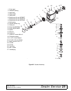
Blade Spindle Disassembly (Figure 13)
Support housing and press blade carrier and shaft (9)
out. Remove seals, bearing cones, and cups from
housing.
1. Blade spindle complete
2. Sleeve
3. Seal
4. Bearing cone
5. Spindle housing with cups
6. Bearing cup
7. Grease fitting
8. Flat washer
9. Spindle shaft and crossbar
10. Blade lock
11. QD Blade pin
12. 1/2 x 3/4" Nylok bolt
13. Blade
Figure 13. Blade Spindle Assembly
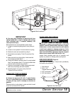
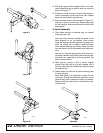
Blade Spindle Assembly (Figure 13)
Bearing cups and cones are designed to work together.
It is important to position them so bearing cone taper
mates with bearing cup taper.
Lubricate new cups (6) with a light oil. Place them in
spindle housing (5) so they will mate with cones (4).
Seat cups (6) against machined shoulder of housing
with a press or by placing a large soft drift on the flat lip
and driving them into housing.
Pack bottom bearing cone (4) with grease and place it
into housing against bearing cup (6).
IMPORTANT
Bearing failure is often a result of improper seal
installation and positioning. Follow instructions
carefully.
Lightly coat housing area where seals seat with Perma-
tex or equivalent.
Lightly lubricate seal, locate spring and place seal
squarely on housing with spring toward housing center.
Select a pipe or tubing with an outside diameter that
will set on outside seal edge. One that is too small will
bow seal cage.
Carefully press seal into housing, preventing distortion
to metal seal cage. Seal should seat firmly and
squarely against machined housing shoulder.
Make sure seal lip did not roll under.
Distortion to seal cage or seal lip damage will cause
leakage. Damaged seals must be replaced.
Place housing assembly over shaft and blade center
(9) and carefully guide over shaft while pressing shaft
into bearing cup and cone. Assembly should seat firmly
against step in shaft.
Fill housing cavity with a lithium grease of No. 2 consis-
tency with a MOLY (molybdenum disulfide) additive.
Pack top bearing cone (4) with grease and place it
(taper down) on shaft. Place sleeve (2) on shaft and
press bearing onto shaft until free play is removed and
there is a slight drag (similar to adjusting automobile
wheel bearings). Check by turning housing on shaft; it
should turn freely.
IMPORTANT
Bearing adjustment is set by pressing sleeve
against bearing until proper adjustment is attained.
Adjustment is maintained by seating split taper
bushing against sleeve.
Adjusting bearings too tightly will shorten their life.
Should you overtighten them, hold housing and rap top
of shaft with a lead hammer to loosen bearings. Adjust
to obtain proper setting.
Proper bearing adjustment is essential to good bearing
life.